Method of configuration a wireless-controlled lighting system

a wireless control and lighting system technology, applied in the direction of electric controllers, frequency-division multiplexes, instruments, etc., can solve the problems of limiting the types of new and replacement lighting units that can be incorporated into the system, additional complications, and lighting units in locations that are not within sight of users, so as to reduce the likelihood of errors in installation

Active Publication Date: 2006-03-09
SIGNIFY HLDG BV
View PDF9 Cites 130 Cited by
  • Summary
  • Abstract
  • Description
  • Claims
  • Application Information

AI Technical Summary

Benefits of technology

[0015] In a preferred form of the invention, each lighting unit in the group includes a convertible device which can operate as either a master or a slave.

Problems solved by technology

In particular, the system must be capable of unambiguously controlling selected lighting units in the system and of incorporating lighting units which are later added to the system.
This system is relatively simple, but since RF signals pass through walls, it can cause the lighting of lighting units in locations that are not within sight of the user.
Further, if the remote is lost or becomes inoperable the entire system must be reconfigured with

Method used


Image

  • Method of configuration a wireless-controlled lighting system
  • Method of configuration a wireless-controlled lighting system
  • Method of configuration a wireless-controlled lighting system

Examples


Embodiment Construction

)

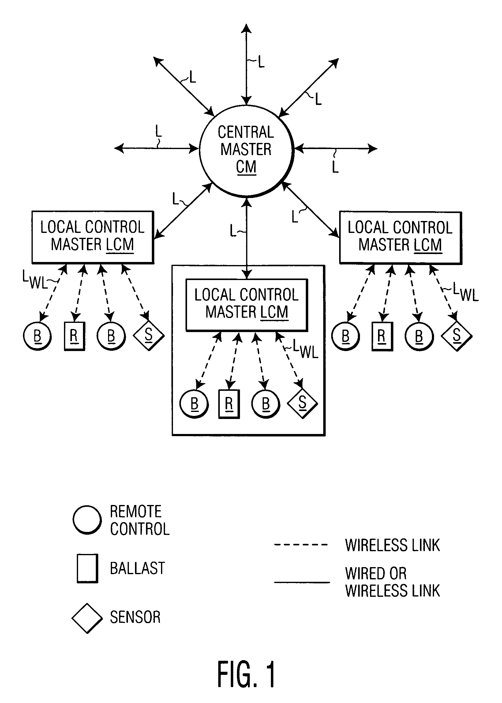
[0020]FIG. 1 illustrates an exemplary lighting-control system in which the invention is utilized. The system shown includes a number of local control masters LCM, each communicating with a central master CM via a wired or wireless link L. The choice of which type of link to be utilized for coupling each individual local control master to the central master is optional and depends on various factors. For example, wired links are commonly used in new lighting installations, while wireless links are commonly used in both retrofit and in new installations.

[0021] The central master CM functions to provide central control and monitoring of the entire lighting system (such as all rooms in a building or building complex), while each local control master LCM functions to provide control and monitoring within a local area (such as within one or more rooms of a building). The local control masters LCM communicate via respective wireless links LWL to lighting-system components including light...


PUM


Abstract

A method for associating a group of lighting units in a wireless-controlled lighting system to respective buttons or other control elements on a remote control. Each of the lighting units transmits, via modulation of its own illumination light, a unique identification code for the respective unit. The remote control is successively positioned to receive the modulated light from each lighting unit and, at each position, the user activates a respective control element of the remote control for association with the lighting unit. The remote control then transmits to a control master for the group the unique codes and codes identifying the respective control elements with which they have been associated.

Description

BACKGROUND OF THE INVENTION [0001] 1. Field of the Invention [0002] This invention relates to wireless-control of lighting systems and, in particular, to the configuration of components within the system. [0003] 2. Description of Related Art [0004] Wireless control of a lighting system provides many advantages besides the ability of remotely switching and dimming lighting units in the system. For example, such control provides a convenient way of setting up and making changes to a lighting system and of improving energy utilization. Features such as emergency lighting control can be added without making any wiring changes. Energy utilization by the system can be regulated by a program which can be readily modified to meet changing demands. [0005] In order for a wireless-controlled lighting system to be readily accepted by users, however, a number of considerations must be addressed. In particular, the system must be capable of unambiguously controlling selected lighting units in the...

Claims


Application Information

Patent Timeline
IPC IPC(8): G08B1/08H05B37/02
CPCH05B37/02H05B37/0272H05B37/0245H05B47/175H05B47/10H05B47/19
Inventor GIANNOPOULOS, DEMETRIWANG, LING
Owner SIGNIFY HLDG BV
Why Eureka
Try Eureka