
Single-pass image warping system and method with anisotropic filtering

an image warping system and single-pass image technology, applied in the field of single-pass image warping system and method with anisotropic filtering, anisotropic, can solve the problems of not all geometrical transformations are separable, dispersed images may have various optical and geometric distortions, and separation itself may introduce geometrical distortions

Active Publication Date: 2006-03-09
QUALCOMM INC
View PDF8 Cites 11 Cited by
  • Summary
  • Abstract
  • Description
  • Claims
  • Application Information

AI Technical Summary

Benefits of technology

The present invention provides a method and system for digital image warping with an anisotropic filter to enhance image quality and detail. The method involves mapping input image data onto an output image space, determining the filter's Jacobian matrix, and extending and adjusting the filter's radii based on image quality and processing speed. The system includes an input interface, coordinates generator, local scale estimator, footprint generator, filter coefficients generator, and output interface. The invention allows for a trade-off between image quality and processing speed, and can be adjusted based on local edge orientation.

Problems solved by technology

The displayed images, however, may have various optical and geometric distortions, such as lens distortions such as pincushion and barrel distortions, projection keystone distortions, and so on.
Firstly, not all geometrical transformations are separable (bottleneck and fold over problems).
Secondly, the separation itself may introduce geometrical distortions.
Thirdly, two-pass filtering is prone to producing jagging artifacts, especially when the geometrical transformation has rotational component.
However, these and other prior art systems provide a modest trade-off between aliasing and sharpness because their impulse responses produce pure frequency responses.

Method used


Image

  • Single-pass image warping system and method with anisotropic filtering
  • Single-pass image warping system and method with anisotropic filtering
  • Single-pass image warping system and method with anisotropic filtering

Examples


Embodiment Construction

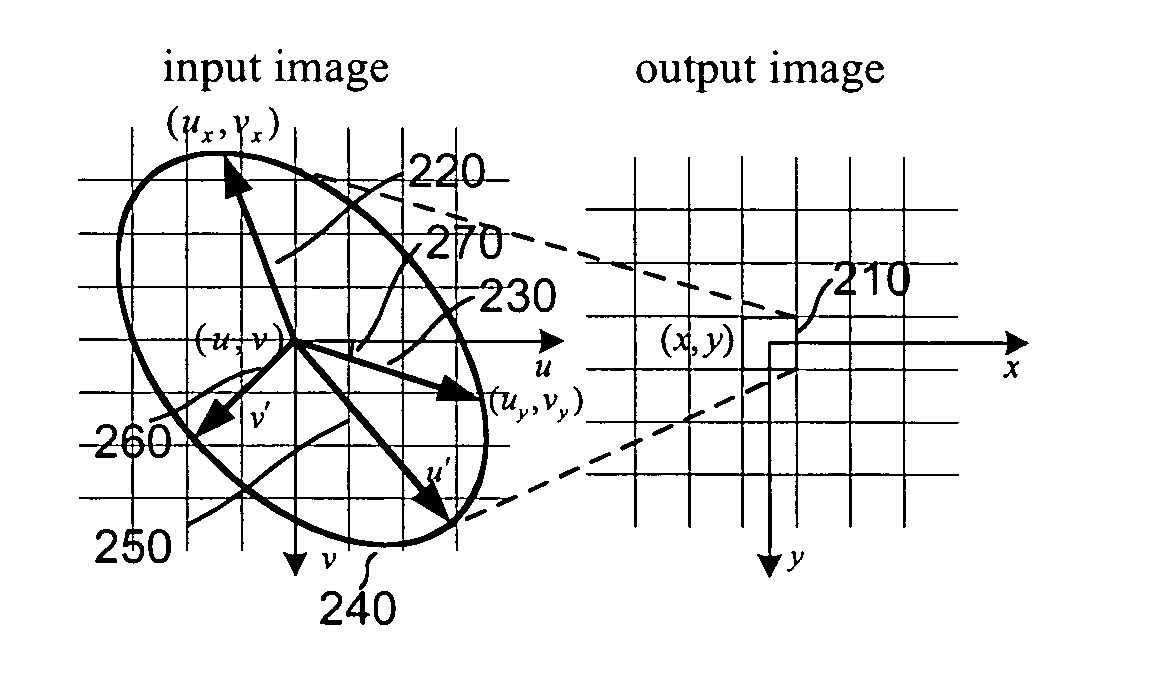
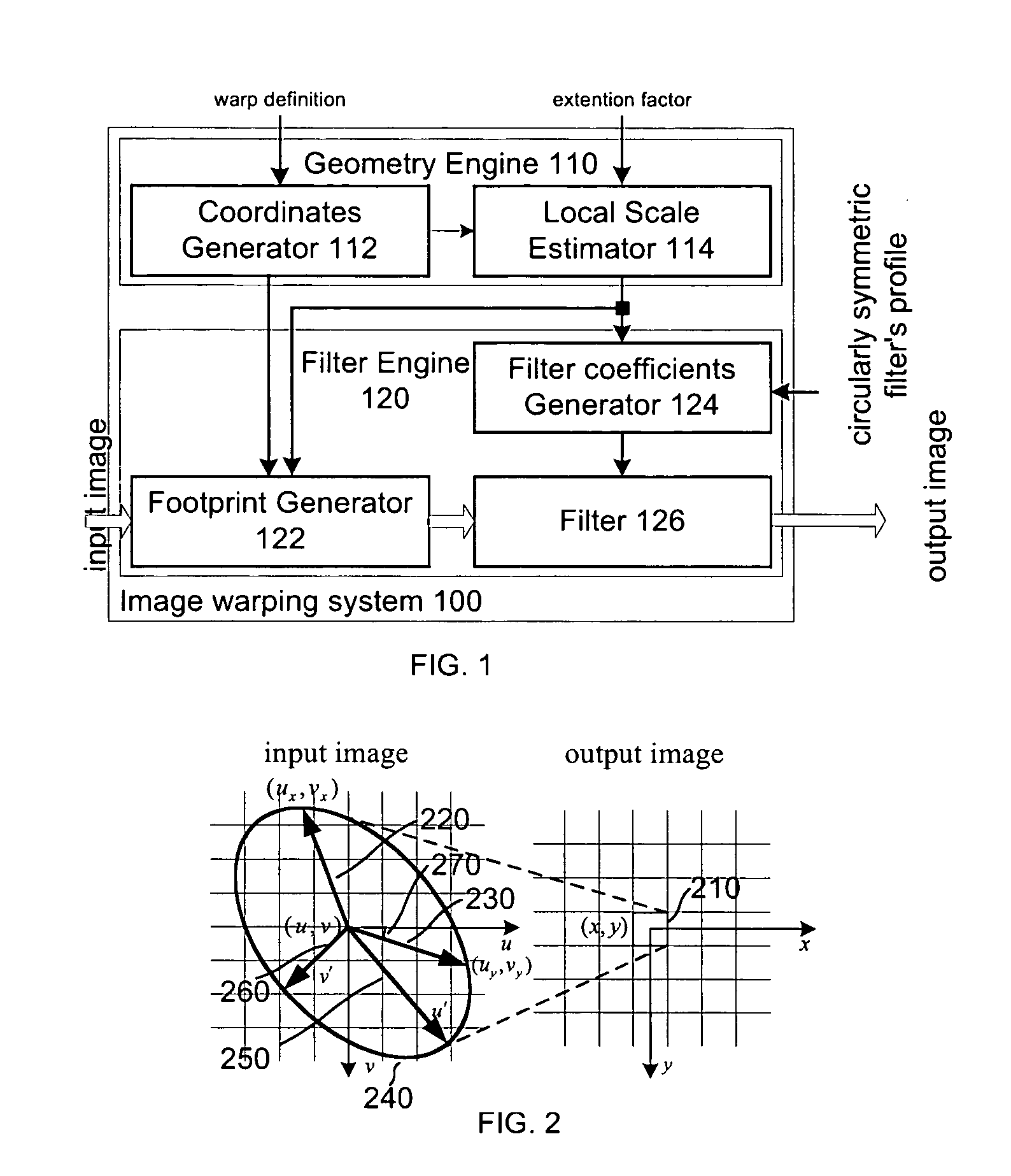
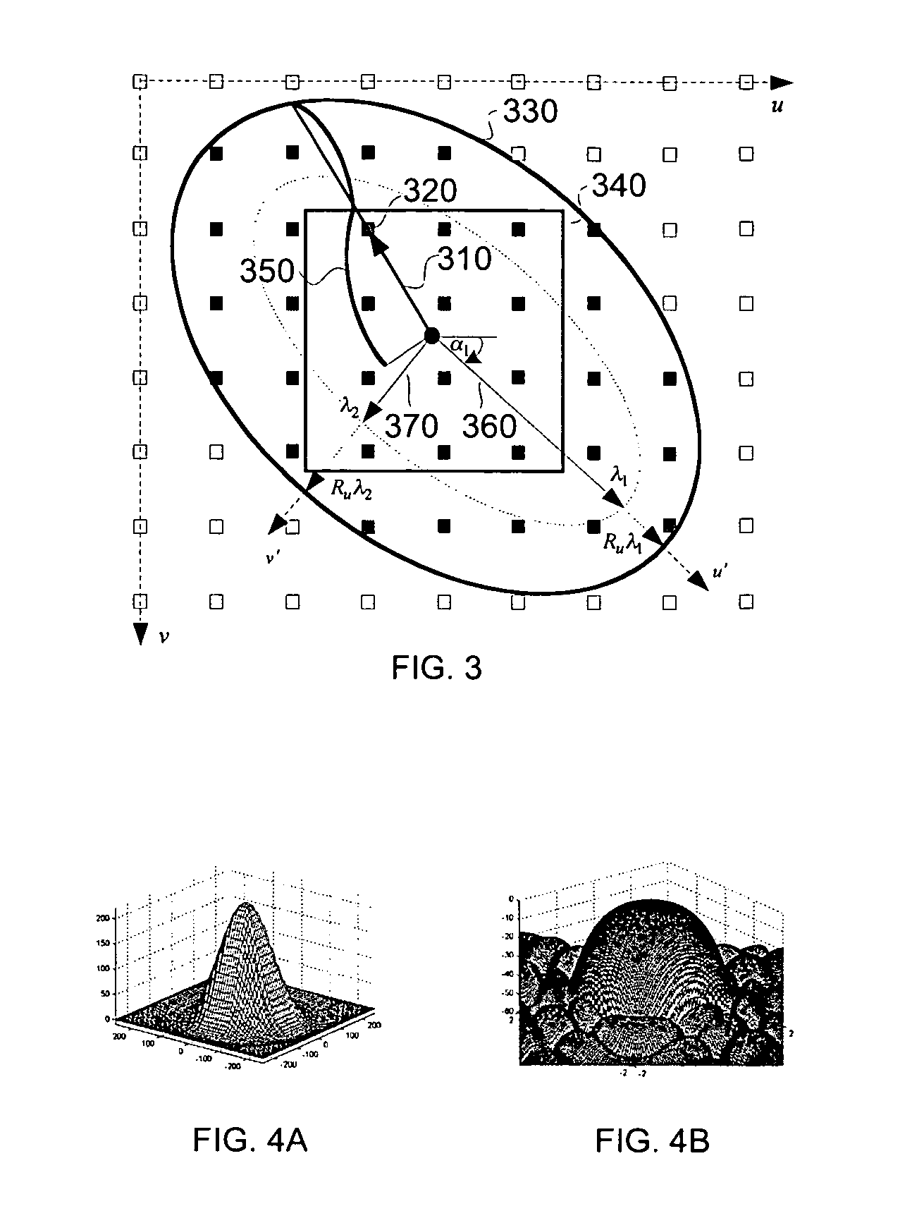
[0049] Reference is first made to FIG. 1 which shows an image warping system 100 made in accordance with a preferred embodiment of the invention. Image warping system 100 is a single-pass digital image warping system with circularly symmetric anisotropic filtering. Image warping system 100 includes a coordinates generator 112, a local scale estimator 114, a footprint generator 122, a filter coefficients generator 124, and a filter 126. The coordinates generator 112 transforms pixel coordinates from an output image space onto an input image space. Local scale estimator 114, calculates parameters of a linear transformation to a unit circle from an ellipse that approximates non-uniform image scaling function in the mapped output pixel. Footprint generator 122 determines input pixels to be participated in the filtering. Filter coefficients generator 124 calculates weights of the input pixels in the footprint using circularly symmetric profile. Finally, filter 126 calculates the output p...


PUM


Abstract

A method and system for circularly symmetric anisotropic filtering over an extended elliptical or rectangular footprint in single-pass digital image warping are disclosed. The filtering is performed by first finding and adjusting an ellipse that approximates a non-uniform image scaling function in a mapped position of an output pixel in the input image space. A linear transformation from this ellipse to a unit circle in the output image space is determined to calculate input pixel radii inside the footprint and corresponding filter coefficient as a function of the radius. The shape of the footprint is determined as a trade-off between image quality and processing speed. In one implementation, profiles of smoothing and warping components are combined to produce sharper or detail enhanced output image. The method and system of the invention produce natural output image without jagging artifacts, while maintaining or enhancing the sharpness of the input image.

Description

FIELD OF THE INVENTION [0001] This invention relates to filtering methods in digital image transformation, and in particular, anisotropic filtering in signal resampling in single-pass digital image warping systems. BACKGROUND OF THE INVENTION [0002] A digital image is basically a two-dimensional array of digital data with each entry representing a pixel of the digitized image. Pixel data contain intensity components like red, green, and blue (RGB). Display systems electronically assign intensity values to these different components based on input digital data. The displayed images, however, may have various optical and geometric distortions, such as lens distortions such as pincushion and barrel distortions, projection keystone distortions, and so on. One way to compensate for these distortions is digital image warping, or “non-uniform scaling”. Image warping may be defined as a process of dynamically resampling a regularly spaced input image to produce an output image with differen...

Claims


Application Information

Patent Timeline
Patent Type & Authority Applications(United States)
IPC IPC(8): G09G5/00
CPCG06T3/0093G06T5/20G06T5/004G06T3/18G06T5/75
Inventor LACHINE, VLADIMIRSMITH, GREGORY LIONELLEE, LOUIE
Owner QUALCOMM INC
Learn More