Projection system for EUV lithography

a projection system and lithography technology, applied in the field of microlithography objectives, can solve the problems of reducing the throughput of the entire projection apparatus, the system is very long (3000 mm), and the examples are not well suited to contemporary lithography at extreme ultraviolet wavelengths, etc., to achieve the effect of efficient masking of undesired light, simple manufacturing and mechanically easy to achiev

Inactive Publication Date: 2006-03-09
CARL ZEISS SMT GMBH
View PDF28 Cites 6 Cited by
  • Summary
  • Abstract
  • Description
  • Claims
  • Application Information

AI Technical Summary

Benefits of technology

[0029] The objective can be used not only in the EUV, but also at other wavelengths, without deviating from the scope of the invention. In any respect, however, to avoid degradation of image quality, especially degradation due to central shading, the mirrors of the projection objectives should be arranged so that the light path of the bundle of light rays traveling from the object plane to the image plane is obscuration-free. Furthermore, to provide easy mounting and adjusting of the system, the physical mirror surfaces have a rotational symmetry to a principal axis (PA). Moreover, to have a compact design with an accessible aperture and to establish an obscuration-free light path of the bundle of light rays traveling from the object plane to the image plane, the projection objective device is designed in such a way that an intermediate image of the object situated in the object plane is formed after the fourth mirror. In such systems, it is possible that the aperture stop is situated in the front, low-aperture objective part, with a pupil plane conjugated to the aperture stop imaged in the focal plane of the last mirror. Such a system ensures telecentricity in the image plane.
[0030] In an preferred embodiment of the invention, the aperture stop is freely accessible and arranged in the light path from the object plane to the image plane between the second and third mirror. Good accessibility of the aperture stop is ensured when the ratio of the distance between the first and third mirror to the distance between the first and second mirror lies in the range of: 0.5<S1S3 / S1S2<2. As defined for the free working distance in general a distance between two mirrors is the distance of the vertices of the surfaces of these mirrors. Furthermore, in order to prevent vignetting of the light running from the third to the fourth mirror, by the aperture stop arranged between the second and third mirror, the ratio of the distance between the second mirror and aperture stop to the distance between the third mirror and the aperture stop lies in the range: 0.5<S2 aperture / (S3 aperture)<2. In such a system, the angles of incidence on the physical mirror surfaces in the front part of the objective are reduced.
[0031] An aperture stop which physically lies between the second mirror, S2, and the first mirror, S1, must be formed at least partially as a narrow ring in order to avoid clipping of light moving from S1 to S2. In such a design, there is a danger that undesirable direct light or light reflected on S1 and S2, will pass outside the aperture ring and reach the image plane and thus the wafer. However, if the aperture stop is placed in the light path between the second and third mirror and physically close to the first mirror (which can be easily achieved mechanically), an efficient masking of this undesired light is possible. The aperture stop can be designed both as an opening in the first mirror or an opening which is arranged behind the first mirror. In another embodiment of the invention, the aperture stop is arranged on or near the second mirror. Arrangement of the aperture on a mirror has the advantage that it is easier to manufacture. In order to ensure an obscuration-free ray path with simultaneously low angles of incidence, the ratio of the distance between the first and third mirrors (S1S3) to the distance between the first and second mirrors (S1S2) lies in the range: 0.3≦S1S3 / S1S2≦2.0, while the ratio of the distance between the second and third mirrors (S2S3) to the distance between the third and fourth mirrors (S3S4) lies in the range: 0.7≦S2S3 / S3S4≦1.4.
[0032] In order to be able to make the necessary corrections of imaging errors in the six-mirror systems, in a preferred embodiment, all six mirrors are designed to be aspherical. However, an alternative embodiment whereby at most five mirrors are aspherical can simplify the manufacturing, because it is then possible to design one mirror, preferably the largest mirror, i.e., the quaternary mirror, in the form of a spherical mirror. Moreover, it is preferred that the second to sixth mirror be in a concave-convex-concave-convex-concave sequence.

Problems solved by technology

This reduction in ring field width results directly in reduced throughput of the entire projection apparatus.
While minimizing the number of reflections has several advantages particular to EUV lithography, an odd number of reflections create a problem in that new stage technology would need to be developed to enable unlimited parallel scanning.
While the embodiments disclosed in the '240 patent appear to achieve their stated purpose, these examples are not well suited for contemporary lithography at extreme ultraviolet wavelengths.
First, the systems are very long (˜3000 mm) and would suffer mechanical stability problems.
Second, the embodiments do not support telecentric imaging at the image which is desired for modern semiconductor lithography printing systems.
Lastly, the numerical aperture is rather small (˜0.05) leaving the systems unable to address 30 nm design rules.
While these systems were designed for DUV lithography and are fine for that purpose, these embodiments make very poor EUV projection systems.
Even after the numerical aperture is reduced from 0.50 to 0.25, the incidence angles of the ray bundles are very large at every mirror including the mask, making the system incompatible with either Mo / Si or Mo / Be multilayers.
While the prior art projection optical systems have proven adequate for many applications, they're not without design compromises that may not provide an optimum solution in all applications.

Method used


Image

  • Projection system for EUV lithography
  • Projection system for EUV lithography
  • Projection system for EUV lithography

Examples


first preferred embodiment

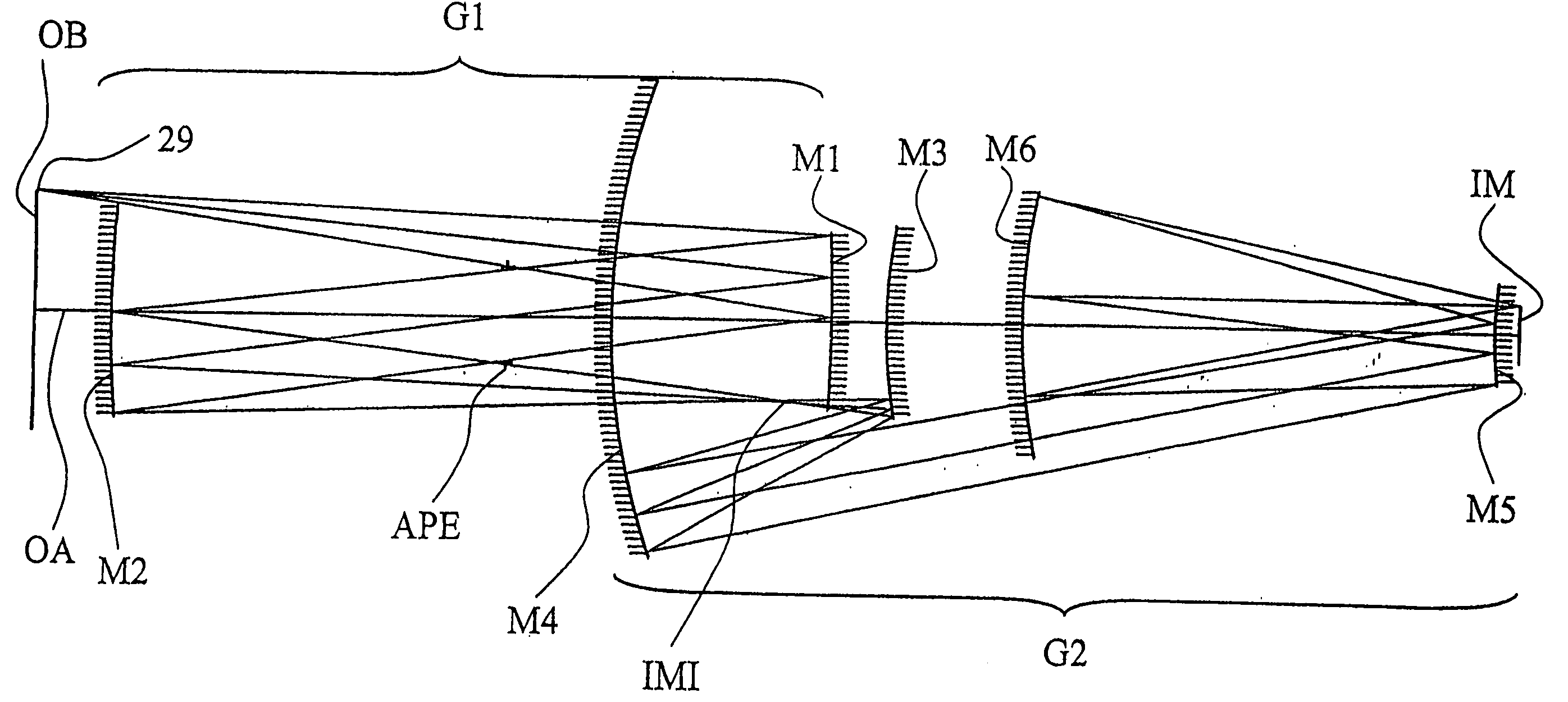
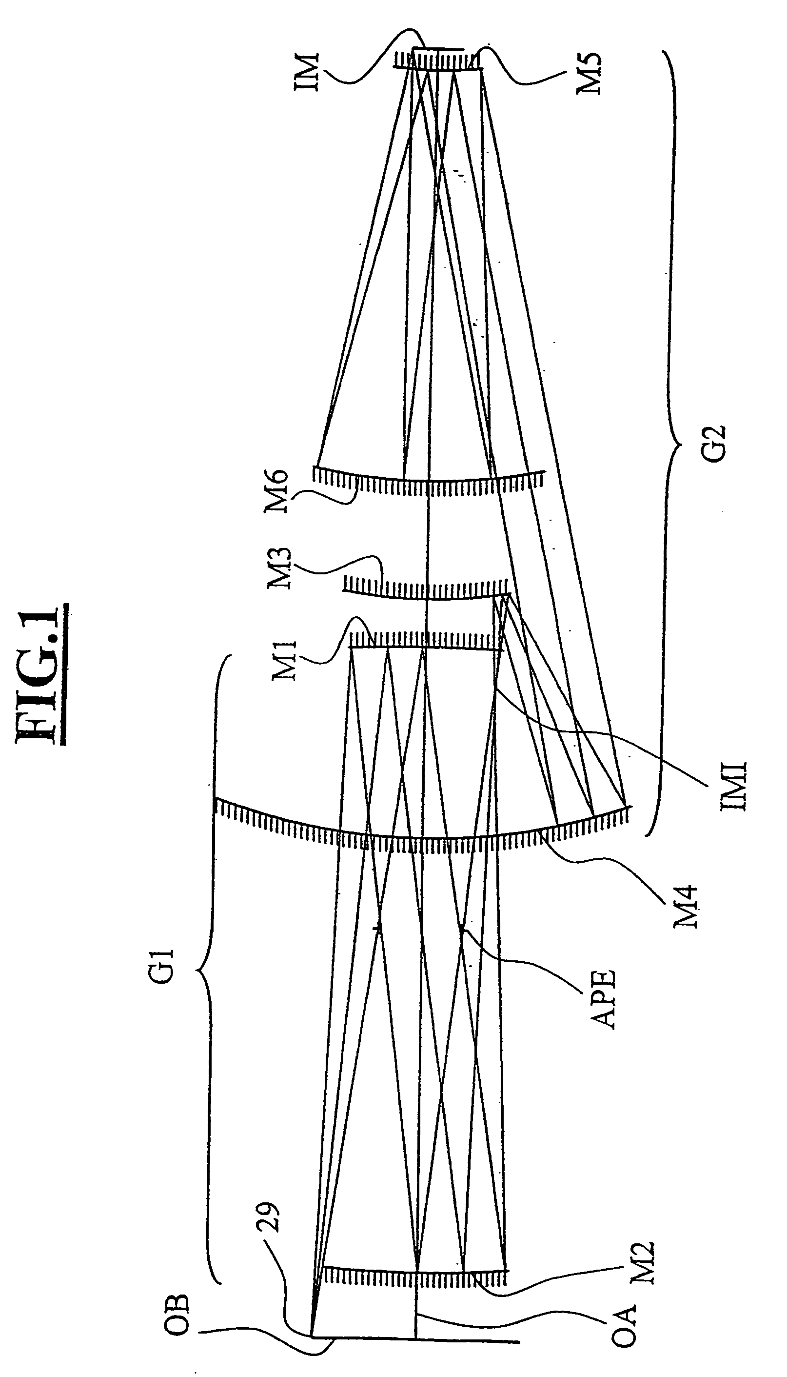
[0061]FIG. 1 shows a plan view of a first preferred embodiment, and, taking in conjunction with Table 1 and Table 2, provides an illustrative, exemplary description of this embodiment. Light impinges on an object, e.g. a reflective mask or reticle from an illumination system and is directed to concave mirror M1 after which it reflects from the mirror M1 and passes through a physically accessible aperture stop APE that is located between Mirror M1 and M2. This aperture stop APE is located a substantial distance from the first concave mirror M1 and, likewise, this aperture stop APE is located a substantial distance from concave mirror M2. After the illumination reflects off concave mirror M2, the light comes to a focus at an intermediate image IMI that is located in close proximity to convex mirror M3. From mirror M3 the illumination is directed toward concave mirror M4 where the light is nearly collimated and directed toward convex mirror M5. Upon reflection from mirror M5, the light...

second preferred embodiment

[0070] In a second of these general embodiments, an optical projection system for extreme ultraviolet (EUV) lithography including six mirrors arranged in a PPNPNP configuration is disclosed. The plan view of this second preferred embodiment is shown in FIG. 3, which demonstrates a PPNPNP configuration designed for EUV lithography at a wavelength of 13.4 nm. Like the first preferred embodiment, the system is reimaging, and unlike the '310 and '079 embodiments, locates the intermediate image IMI′ before the second mirror pair. In this example, the intermediate image IMI′ is located between mirror M2′ and M3′, helping to promote low incidence angle variation across mirror M5′. This construction also enables low mean incidence angles on mirror M1′, M2′, M4′, and M6′. These low incidence angles are advantageous for maintaining good multilayer compatibility. The aperture stop APE′ is located between M1′ and M2′ and is significantly spaced from either mirror, e.g., more than 200 mm.

[0071]...

third preferred embodiment

[0077] The third preferred embodiment is shown in FIG. 4. Like the first and second preferred embodiments, this system utilizes a re-imaging PPNPNP configuration with a physically accessible aperture stop APE″ that is located between the primary mirror M1″ and secondary mirror M2″. And like the first and second embodiments, the intermediate image IMI″ is located between the secondary mirror M2″ and the tertiary mirror M3″. Similar to the second embodiment, the tertiary mirror M3″ is located on the object side of the primary mirror M1″. This particular embodiment differs from the second preferred embodiment in that the chief ray CR″ from the central field point 29″ converges toward the optical axis OA″ after reflection from the secondary mirror M2″, thus forming another advantageous projection system with distinct characteristics.

[0078] The optical prescription for this third embodiment of FIG. 4 is listed in Table 7 and Table 7. Table 7 lists the vertex radius of curvature as well ...


PUM

PropertyMeasurementUnit
physical distanceaaaaaaaaaa
incidence angleaaaaaaaaaa

Abstract

An EUV optical projection system includes at least six reflecting surfaces for imaging an object (OB) on an image (IM). The system is preferably configured to form an intermediate image (IMI) along an optical path from the object (OB) to the image (IM) between a secondary mirror (M2) and a tertiary mirror (M3), such that a primary mirror (M1) and the secondary mirror (M2) form a first optical group (G1) and the tertiary mirror (M3), a fourth mirror (M4), a fifth mirror (M5) and a sixth mirror (M6) form a second optical group (G2). The system also preferably includes an aperture stop (APE) located along the optical path from the object (OB) to the image (IM) between the primary mirror (M1) and the secondary mirror (M2). The secondary mirror (M2) is preferably concave, and the tertiary mirror (M3) is preferably convex. Each of the six reflecting surfaces preferably receives a chief ray (CR) from a central field point at an incidence angle of less than substantially 15°. The system preferably has a numerical aperture greater than 0.18 at the image (IM). The system is preferably configured such that a chief ray (CR) converges toward the optical axis (OA) while propagating between the secondary mirror (M2) and the tertiary mirror (M3).

Description

CROSS-REFERENCE TO RELATED APPLICATIONS [0001] The present application is a continuation of International Application No. PCT / EP01 / 14301 and a continuation-in-part of U.S. patent application Ser. No. 10 / 004,674. The PCT / EP01 / 14301 application was filed Dec. 6, 2001, and claims priority of U.S. Provisional Patent Application Ser. No. 60 / 255,161, which was filed Dec. 12, 2000. The 10 / 004,674 application was filed Mar. 12, 2001 and is a continuation-in-part of U.S. patent application Ser. No. 09 / 503,640. The 09 / 503,640 application was filed Feb. 14, 2000 and issued as U.S. Pat. No. 6,353,470. The present application is also claiming priority of (a) German Patent Application No. 199 06 001 filed Feb. 15, 1999, and (b) German Patent Application No. 199 48 240 filed Oct. 7, 1999.BACKGROUND OF THE INVENTION [0002] 1. Field of the Invention [0003] The present invention relates to a microlithography objective, a projection exposure apparatus containing the objective, and a method of manufact...

Claims


Application Information

Patent Timeline
Patent Type & Authority Applications(United States)
IPC IPC(8): G03B27/54G02B13/24G02B11/00G02B17/06G03F7/20H01L21/027
CPCG02B17/0652G02B17/0657G03F7/70275G03F7/70233G03B27/54
Inventor HUDYMA, RUSSELLMANN, HANS-JURGENDINGER, UDO
Owner CARL ZEISS SMT GMBH
Why Eureka
Try Eureka