Micro-actuator, head gimbal assembly, and disk drive unit with the same

a head gimbal and micro-actuator technology, applied in the direction of data recording, magnetic recording, instruments, etc., can solve the problem of parallel gap between the suspension and the bottom plate, and achieve the effect of good resonance performance and fine head position adjustmen

Inactive Publication Date: 2006-03-09
SAE MAGNETICS (HK) LTD
View PDF33 Cites 56 Cited by
  • Summary
  • Abstract
  • Description
  • Claims
  • Application Information

AI Technical Summary

Benefits of technology

[0009] A main feature of the present invention is to provide a micro-actuator and a HGA which can attain a fine head position adjustment and a good resonance performance when exciting the micro-actuator.

Problems solved by technology

In addition, a parallel gap exists between the suspension and the bottom plate.

Method used


Image

  • Micro-actuator, head gimbal assembly, and disk drive unit with the same
  • Micro-actuator, head gimbal assembly, and disk drive unit with the same
  • Micro-actuator, head gimbal assembly, and disk drive unit with the same

Examples


Embodiment Construction

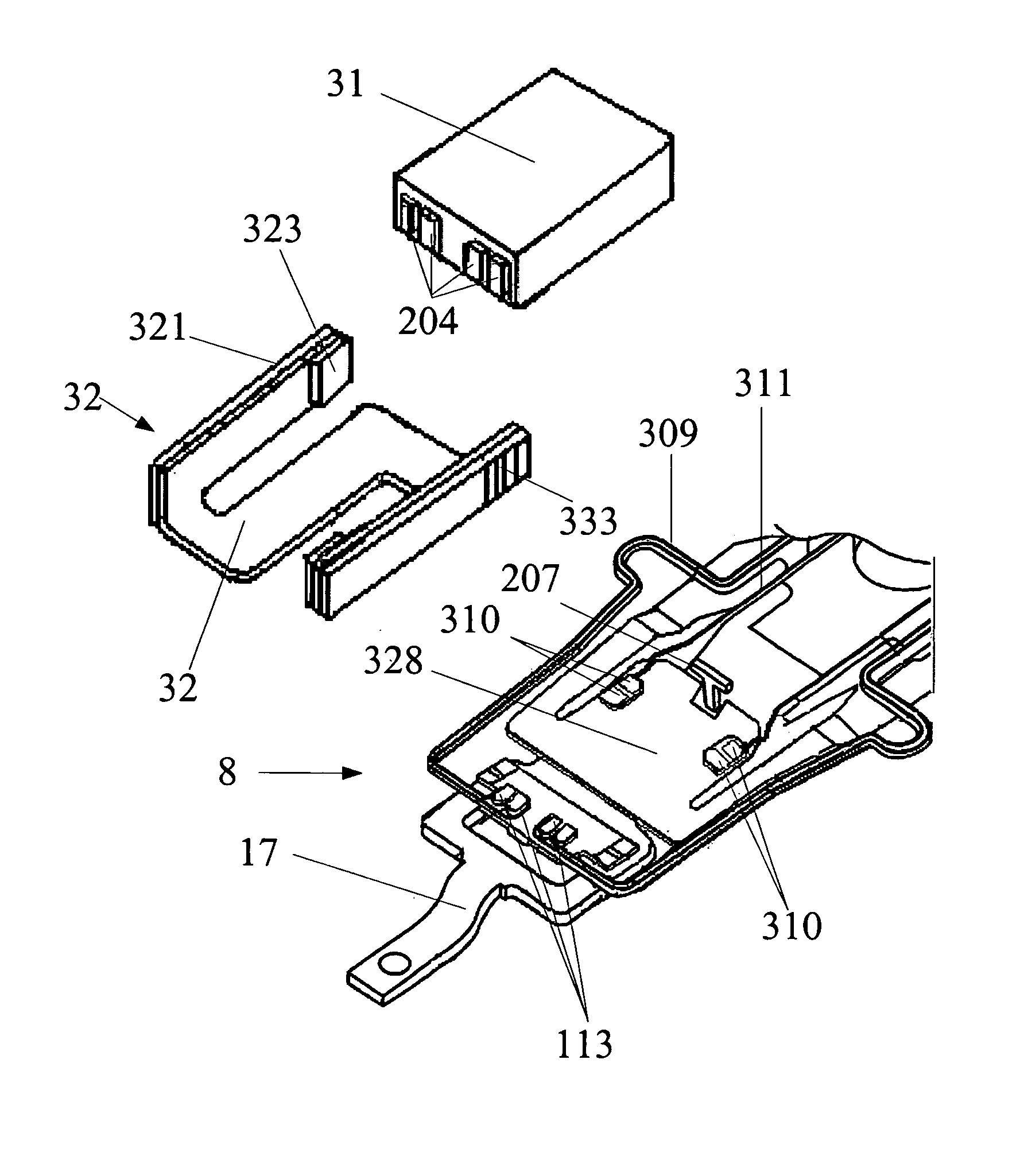
[0045] Referring to FIG. 3, a head gimbal assembly (HGA) 3 of the present invention comprises a slider 31, a micro-actuator 32 and a suspension 8 to load the slider 31 and the micro-actuator unit 32.

[0046] Also referring to FIG. 3, the suspension 8 comprises a load beam 17, a flexure 13, a hinge 15 and a base plate 11. The load beam 17 has a plurality of dimples 329 (see FIG. 6) formed thereon. On the flexure 13 a plurality of connection pads 308 are provided to connect with a control system (not shown) at one end and a plurality of electrical multi-traces 309, 311 is provided in the other end. Referring to FIGS. 4 and 5, the flexure 13 also comprises a suspension tongue 328 which are used to support the micro-actuator 32 and the slider 31, and keep the loading force always being applied to the center area of the slider 31 through the dimples 329 of the load beam 17.

[0047] Referring to FIGS. 4-6, a limiter 207 is formed on the load beam 17 which extends through the suspension tong...


PUM

PropertyMeasurementUnit
piezoelectricaaaaaaaaaa
displacementaaaaaaaaaa
surface recording densityaaaaaaaaaa

Abstract

A head gimbal assembly includes a slider, a rotatable micro-actuator and a suspension to load the slider and the rotatable micro-actuator. The rotatable micro-actuator horizontally rotates the slider with a central portion of the slider as an axis, which includes a bottom plate to be connected with the suspension, two arm plates symmetrically disposed on the bottom plate with a central portion of the bottom plate as symmetry point and at least one piezoelectric pieces to be connected with the arm plates. Selectively, the amount of the arm plates can be four and four piezoelectric pieces to be connected with the four arm plates, respectively.

Description

FIELD OF THE INVENTION [0001] The present invention relates to disk drive units, and particularly relates to a micro-actuator, and a head gimbal assembly using the micro-actuator. BACKGROUND OF THE INVENTION [0002] Disk drives are information storage devices that use magnetic media to store data. Referring to FIG. 1a, a typical disk drive in related art has a magnetic disk and a drive arm to drive a head gimbal assembly 277 (HGA) (the HGA 277 has a suspension (not labeled) with a slider 203 mounted thereon). The disk is mounted on a spindle motor which causes the disk to spin and a voice-coil motor (VCM) is provided for controlling the motion of the drive arm and thus controlling the slider 203 to move from track to track across the surface of the disk to read data from or write data to the disk. [0003] However, Because of the inherent tolerance resulting from VCM and the suspension that exists in the displacement (off track) of the slider 203, the slider 203 can not attain a fine p...

Claims


Application Information

Patent Timeline
Patent Type & Authority Applications(United States)
IPC IPC(8): G11B5/56
CPCG11B5/5552
Inventor YAO, MINGGAOSHIRAISHI, MASASHI
Owner SAE MAGNETICS (HK) LTD
Why Eureka
Try Eureka