Oscillating weight

a technology of oscillating weight and weight, applied in the direction of timer, electromechanical clock, time indication, etc., can solve the problems of large taxation on barrel springs and inability to rule out the risk of excessive wear, and achieve the effect of high adjustment precision

Active Publication Date: 2006-03-09
HOROMETRIE SA
View PDF2 Cites 12 Cited by
  • Summary
  • Abstract
  • Description
  • Claims
  • Application Information

AI Technical Summary

Benefits of technology

[0013] In a variant allowing a high level of adjustment precision, one of the inertia blocks can occupy a finite number n of positions defined such that the passage of said inertia block from one of the positions to another causes a radial movement of the center of gravity of a value ΔG, and so that the second inertia block is arranged so as to be able to occupy a number m of positions where the passage from one position to another causes a radial movement of the center of gravity of a value Δg, said inertia blocks being arranged such that the product m.Δg is substantially equal to ΔG. Consequently, it is possible to define m.n adjustment positions, without the indexing means becoming too complex.

Problems solved by technology

Consequently, with a very active person, the barrel spring is greatly taxed and the risk of excessive wear cannot be ruled out.

Method used


Image

  • Oscillating weight
  • Oscillating weight
  • Oscillating weight

Examples


Embodiment Construction

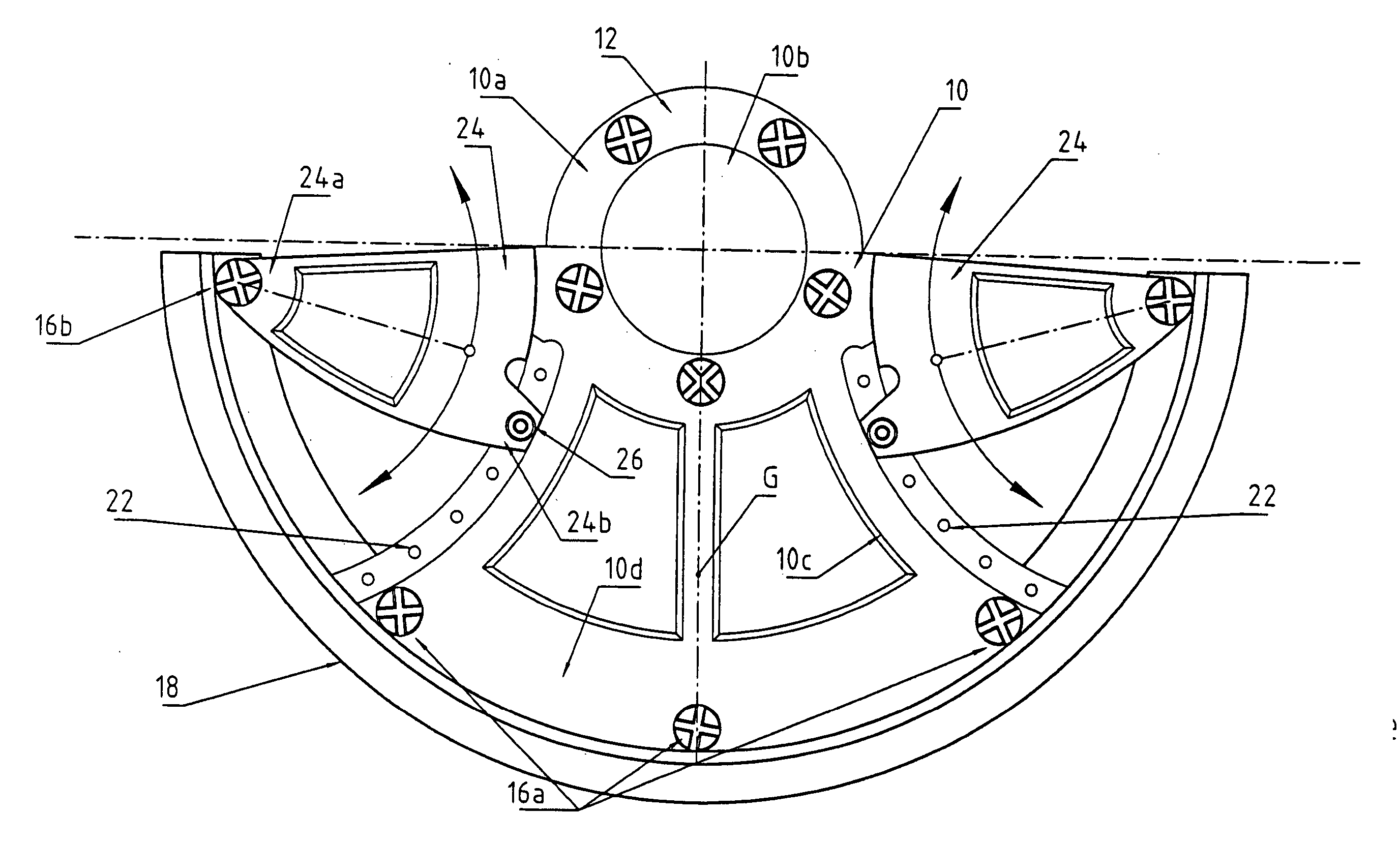
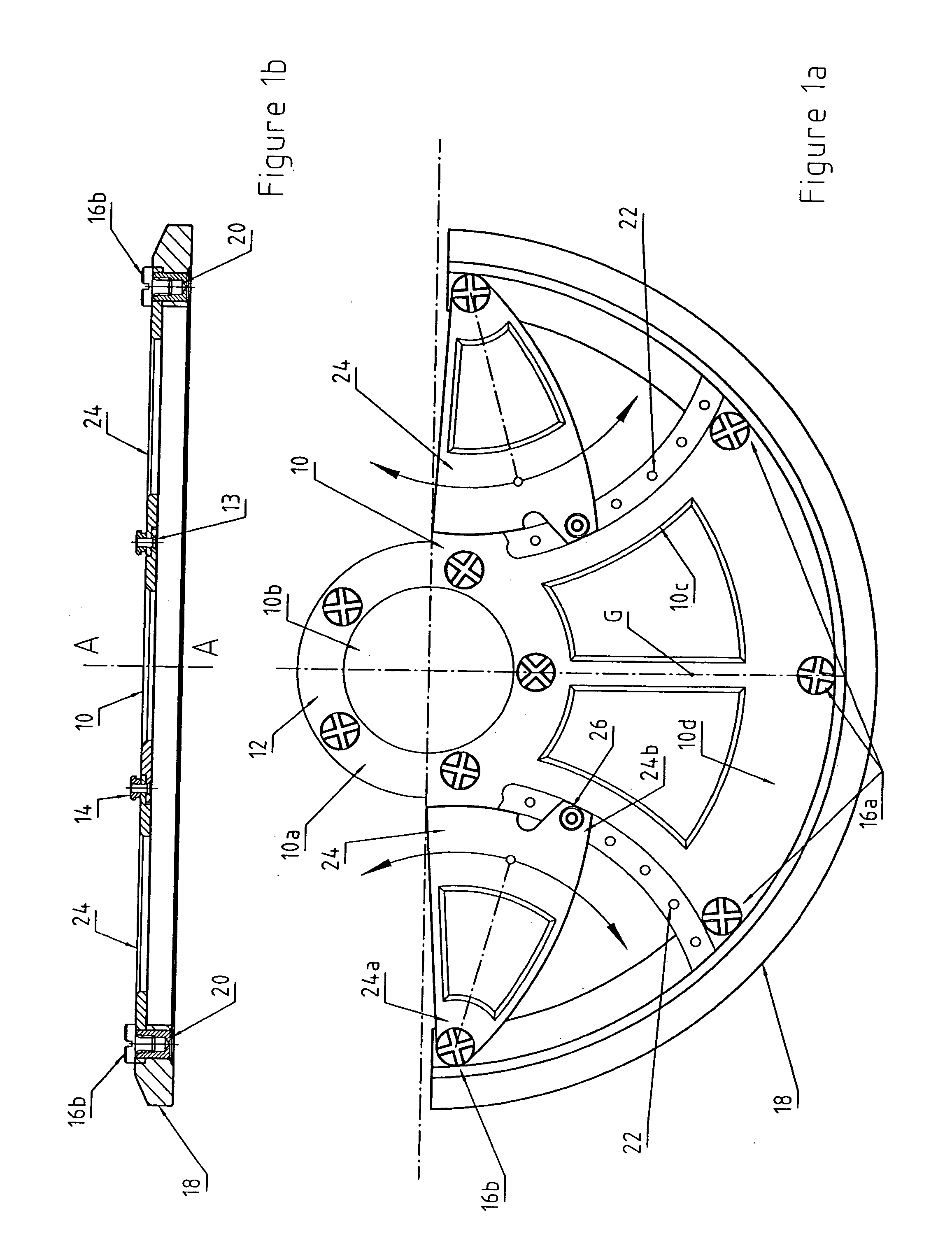
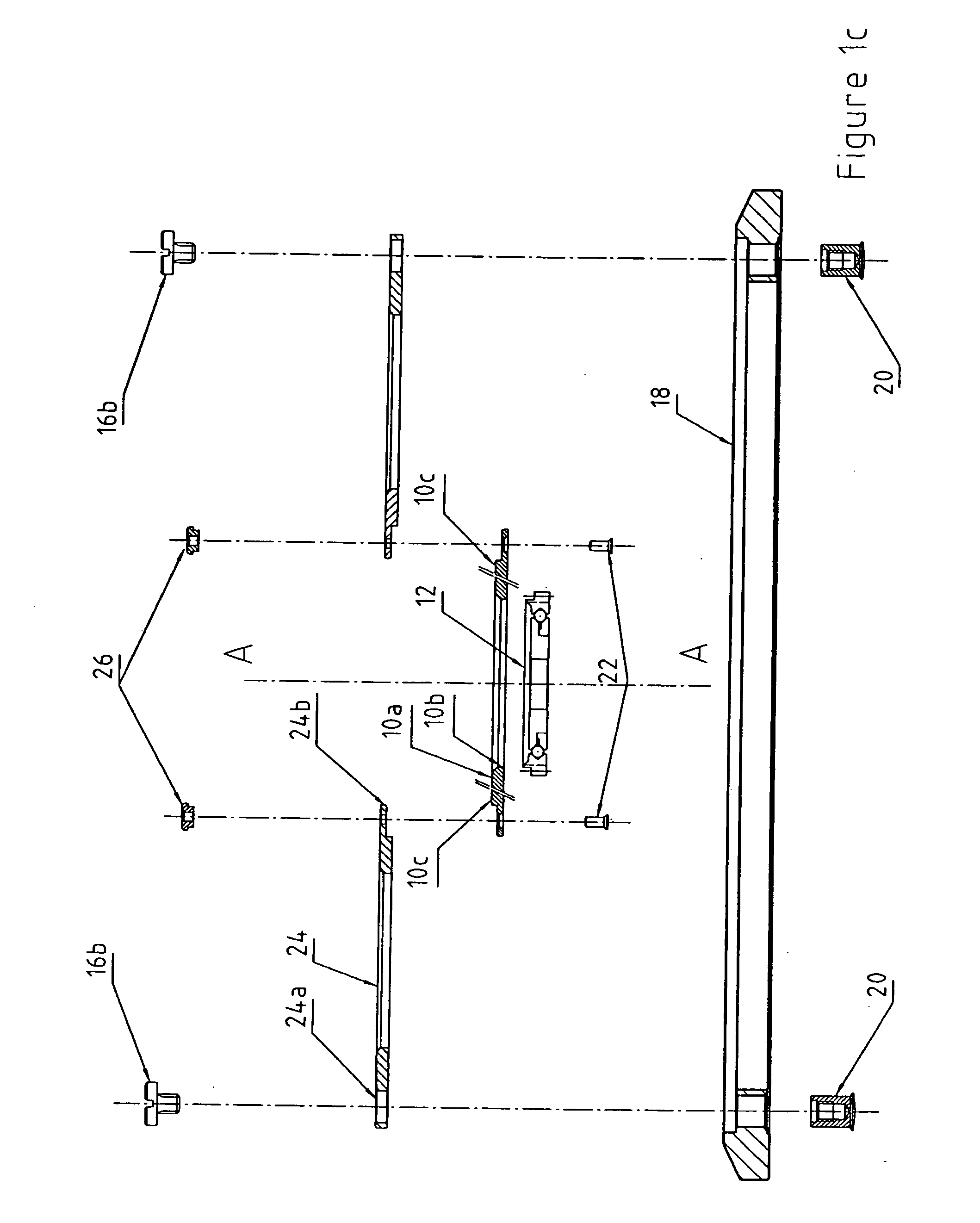
[0024] The weight shown in FIG. 1 includes a plate 10 comprising a central portion 10a of generally annular shape, provided with a central aperture 10b for receiving a bearing 12 that is partially shown, for example a ball bearing, and arms 10c extending radially outwards. The central aperture 10b is circular, defined by a circle of axis A-A.

[0025] In its central portion 10a, plate 10 carries, arranged in a ring, threaded pins 13 for securing bearing 12 by means of bolts 14.

[0026] At their periphery, arms 10c are connected by an annular center portion 10d disposed on axis A-A. It is provided with three holes in which screws 16a are engaged.

[0027] A sector of inertia 18, in the form of an annular portion, is provided with five threaded feet 20. It is secured to plate 10 by means of screws 16a engaged in three of threaded feet 20. It is advantageously made of a heavy material, for example gold or platinum in top of the range watches, of brass for more common products. It extends ov...


PUM


Abstract

Oscillating weight for an automatic watch, arranged to carry a bearing defining an axis of rotation (A-A) and intended to be mounted on the frame of the watch, including a mass member having a centre of gravity (G) shifted with respect to the axis of rotation. In this weight, this mass member includes:
    • two parts that can be moved one (10, 18) in relation to the other (24), and arranged such that their relative movement causes a radial movement of the centre of gravity (G) of the mass member, and
    • a securing device (13, 14, 16b) cooperating with the first and second parts, capable of occupying a first state in which said parts can be moved with reference to each other, and a second state in which said parts are rigidly secured to each other.

Description

FIELD OF THE INVENTION [0001] The present invention concerns automatic watches. It relates more particularly to oscillating weights. BACKGROUND OF THE INVENTION [0002] Automatic watches comprise a movement fitted with a time base, a gear train synchronized by the time base, an energy accumulator, generally a barrel, powering the time base and driving the gear train, and an automatic mechanism supplying energy to the energy accumulator. [0003] Conventionally, this mechanism comprises an oscillating weight, pivotably mounted on the frame of the movement by means of a bearing, a reverser converting the alternating movement of the weight into a rotational movement in one direction, and a winding train, which is of the reduction train type, driven by the reverser. The oscillations of the weight, generated by the movements of the person wearing the watch, thus drive in rotation the winding train, which cooperates with the barrel to wind its spring. [0004] The oscillating weight is arrange...

Claims


Application Information

Patent Timeline
Patent Type & Authority Applications(United States)
IPC IPC(8): G04B1/00G04C3/00G04B5/16
CPCG04B5/165G04B5/188
Inventor PAPI, ALBERTO
Owner HOROMETRIE SA
Why Eureka
Try Eureka