Single use syringe having safety shield

a single-use, safety shield technology, applied in the direction of intravenous devices, infusion needles, infusion devices, etc., can solve the problems of accidental needle sticks from used hypodermic needles transmitting disease, and achieve the effect of shortening the length of the plunger and reducing the thickness of the cross-sectional area

Active Publication Date: 2006-03-09
BECTON DICKINSON & CO
View PDF4 Cites 98 Cited by
  • Summary
  • Abstract
  • Description
  • Claims
  • Application Information

AI Technical Summary

Benefits of technology

[0011] A single use syringe of the present invention comprises a barrel including a cylindrical side wall having an inside surface defining a chamber for retaining fluid. The barrel includes an open proximal end and a distal end having a distal wall with an elongate tip extending distally therefrom having a passageway therethrough in fluid communication with the chamber. A needle cannula having a proximal end, a distal end and a lumen therethrough is connected to the elongate tip so that the lumen is in fluid communication with the passageway of the tip. The connection of the needle cannula to the tip can be either directly or indirectly through a hub attached to the needle cannula. An elongate needle shield is hingedly connected to the barrel. The needle shield includes two sidewalls defining a longitudinal opening and a back wall between the sidewalls defining a recess having an interior surface. The needle shield is capable of pivoting from an open position wherein the needle cannula is exposed, to a closed needle protecting position wherein the distal end of the needle cannula is within the longitudinal opening of the shield. A plunger including an elongate body portion having a proximal portion and a distal portion and a stopper is slidably positioned in fluid-tight engagement with the inside surface of the barrel for drawing fluid into and driving fluid out of the chamber by movement of the stopper relative to the barrel. The elongate body portion extends outwardly from the open proximal end of the barrel. The syringe assembly further includes means for locking the plunger in the barrel by applying an additional distally directed force to the plunger after fluid has been delivered from the chamber.
[0012] The syringe assembly may also include plunger weakening structure for allowing the plunger to break upon application of excessive force intended to move the plunger proximally after the plunger has been locked in the barrel. This structure may take the form of a reduced cross-sectional thickness in the proximal portion of the elongate body portion of the plunger.
[0013] Means for locking the plunger to the barrel may include a contractible portion on the plunger, a discontinuity on the plunger and a discontinuity on the barrel. The plunger discontinuity is capable of eng...

Problems solved by technology

Although many of these devices work quite well, they do require the specific intent of the user followed by the actual...

Method used


Image

  • Single use syringe having safety shield
  • Single use syringe having safety shield
  • Single use syringe having safety shield

Examples


Embodiment Construction

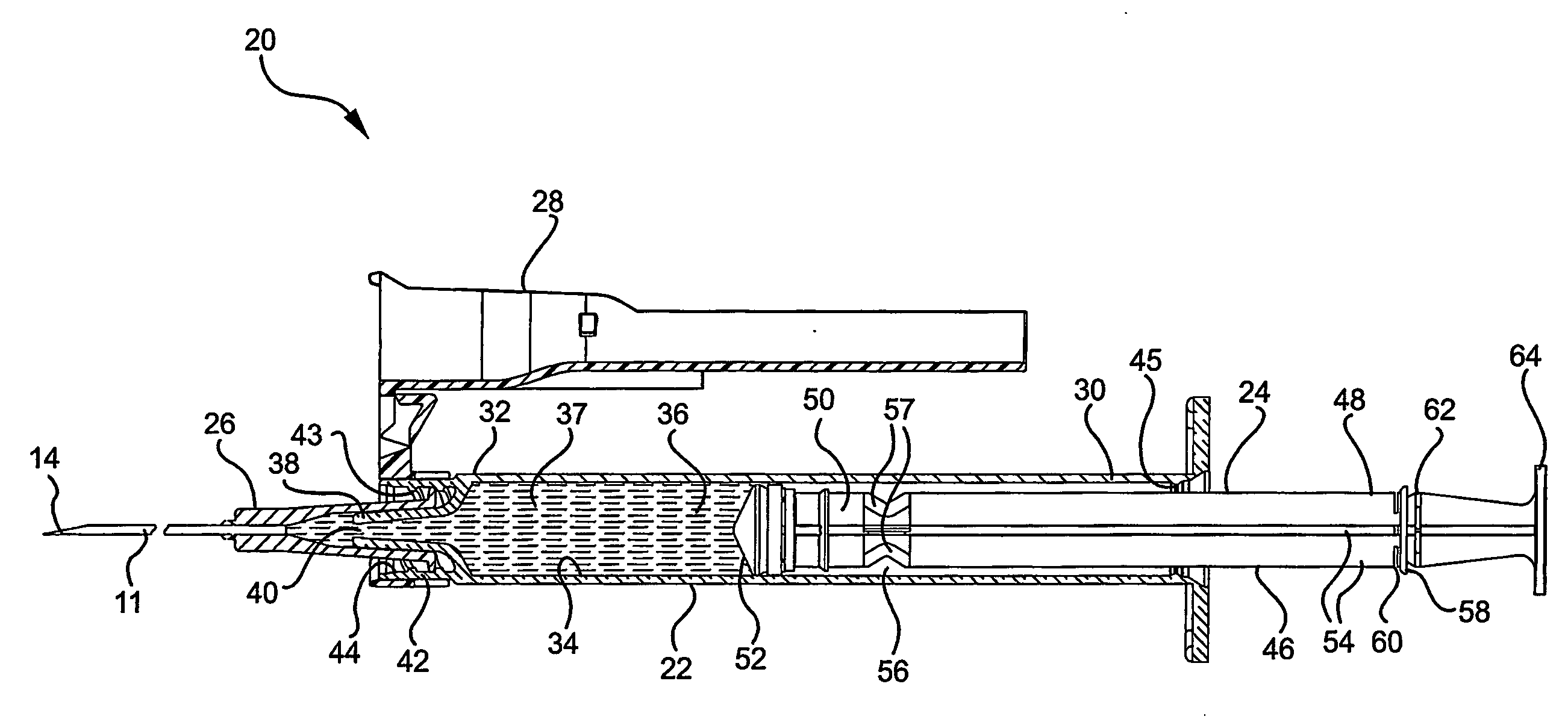
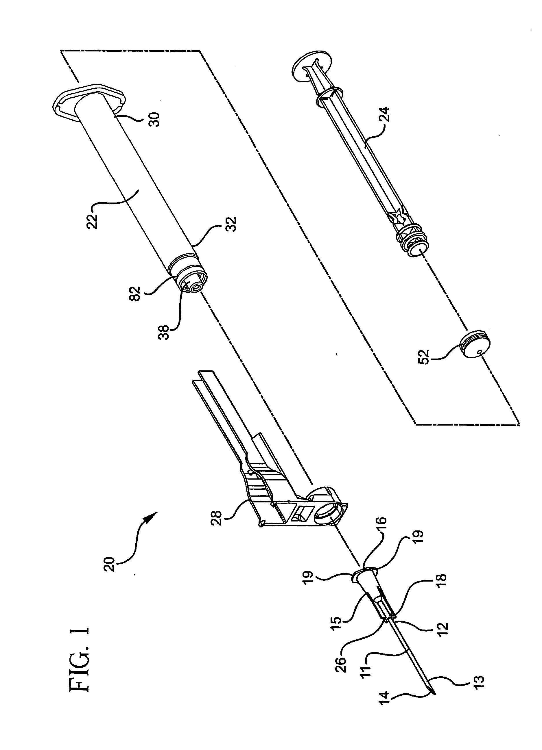
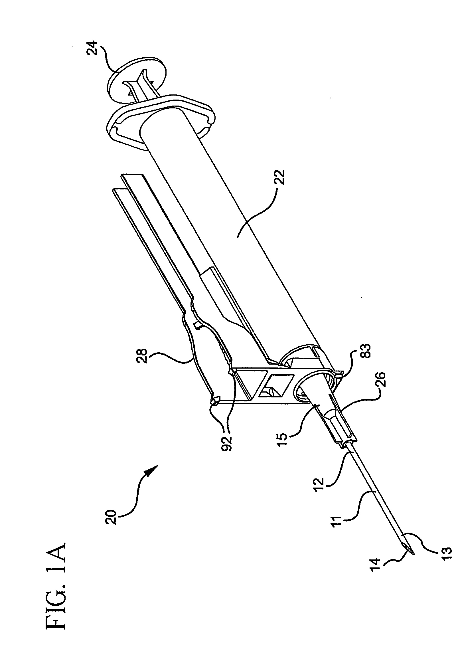
[0038] Referring to FIGS. 1-5A, a syringe assembly 20 according to the present invention, generally comprises a barrel 22, a plunger 24, a needle assembly 26 and a safety shield assembly 28.

[0039] Barrel 22 includes a proximal end 30, a distal end 32, an inside surface 34, a fluid chamber 36 and an elongate tip 38 extending from distal end 32 having a passageway 40 therethrough in fluid communication with chamber 36. The barrel further includes a collar 42 around elongate tip 38 having a thread 43 on an inside surface 44 of the collar. This configuration is often referred to as a locking luer collar. The present invention contemplates the utilization of any type of syringe barrel and needle or needle assembly assembly, and not just a syringe having a locking luer collar. Thus, embodiments of the present invention may include an integral needle and syringe barrel, a luer slip tip with or without a collar, or any other needle / syringe configuration. A discontinuity such as locking pro...


PUM


Abstract

A single use syringe assembly includes a barrel having a chamber for retaining fluid, an open proximal end and a distal end including an elongate tip extending distally therefrom having a passageway therethrough in fluid communication with the chamber. A needle cannula having a lumen therethrough is connected to the elongate tip so that the lumen is in fluid communication with the passageway. An elongate needle shield having a longitudinal opening therein is hingedly connected to the barrel. A needle shield is capable of pivoting from an open position or a closed needle protecting position. The plunger including an elongate body portion and a stopper is slidably positioned in fluid-tight engagement with the inside surface of the barrel. Structure is provided for locking the plunger in the barrel by applying distally directed force to the plunger after fluid has been delivered from the chamber.

Description

BACKGROUND OF THE INVENTION [0001] The present invention relates generally to single use syringes having safety features and more specifically to a single use syringe having a plunger locking mechanism and safety shield. [0002] In the United States and throughout the world, the multiple use of hypodermic syringe products that are intended for single use only, is instrumental in drug abuse and more particularly in the transfer of diseases. Intravenous drug users who routinely share and reuse syringes are a high-risk group with respect to the bloodborne pathogens including HIV and AIDS. Also the effects of multiple use are a major concern in under-developed countries where repeated use of syringe products may be responsible for the spread of many diseases. Reuse of single use hypodermic syringe assemblies is instrumental in the spread of drug abuse even in the absence of infection or disease. [0003] Many attempts have been made to remedy this problem. Some of these attempts have requi...

Claims


Application Information

Patent Timeline
IPC IPC(8): A61M5/00A61M5/32A61M5/315A61M5/50
CPCA61M5/31513A61M5/3216A61M2005/5073A61M5/502A61M5/5066A61M5/347A61M5/32A61M5/50
Inventor COELHO, EDUARDO PINTODA SILVA, DELMAR FRANCISCO GONCALVESSHARIFI-MEHR, AMIRAFLEISCHER, GENECIPOLETTI, ROBERTKODELL, ROBERTB
Owner BECTON DICKINSON & CO
Why Eureka
Try Eureka