Management of thermal fluctuations in lean NOx adsorber aftertreatment systems

a technology of aftertreatment system and thermal fluctuation, which is applied in the direction of exhaust gas recirculation, exhaust treatment, and addition of non-fuel substances to fuels. it can solve the problems of deterioration rate, performance deterioration of current lna washcoats, and interference with the ability of lna to remove nox

Inactive Publication Date: 2006-03-16
WESTPORT POWER
View PDF19 Cites 29 Cited by
  • Summary
  • Abstract
  • Description
  • Claims
  • Application Information

AI Technical Summary

Problems solved by technology

As discussed in, by way of example, U.S. Pat. No. 6,393,834, sulfur poisoning of LNAs from oxides of sulfur in the exhaust gas can interfere with the ability of the LNA to remove NOx.
The performance of current LNA washcoats tends to deteriorate, mainly due to sintering, when exposed to temperatures in excess of 700° C. Exceeding 700° C. by a significant margin increases the rate of deterioration.
De-sulfation temperatures can approach and exceed 700° C. leading to poor long-term performance of the LNA.
However, the LNA reactive capacity (the ability of the LNA to trap NOx) is relatively low at the temperature needed for the effective operation of the reformer / oxidation catalyst.

Method used

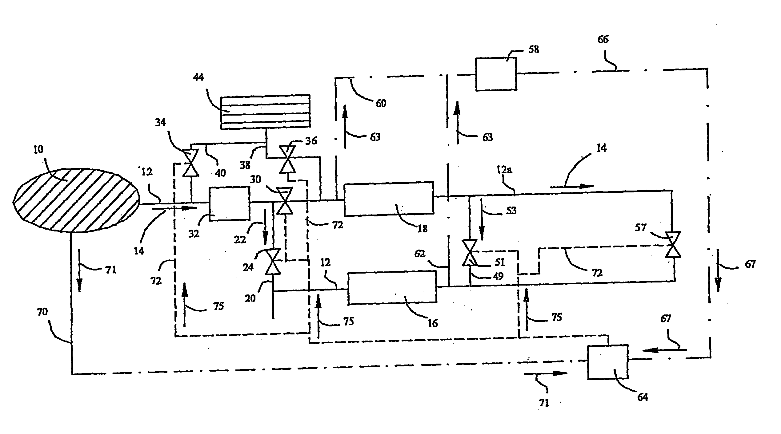
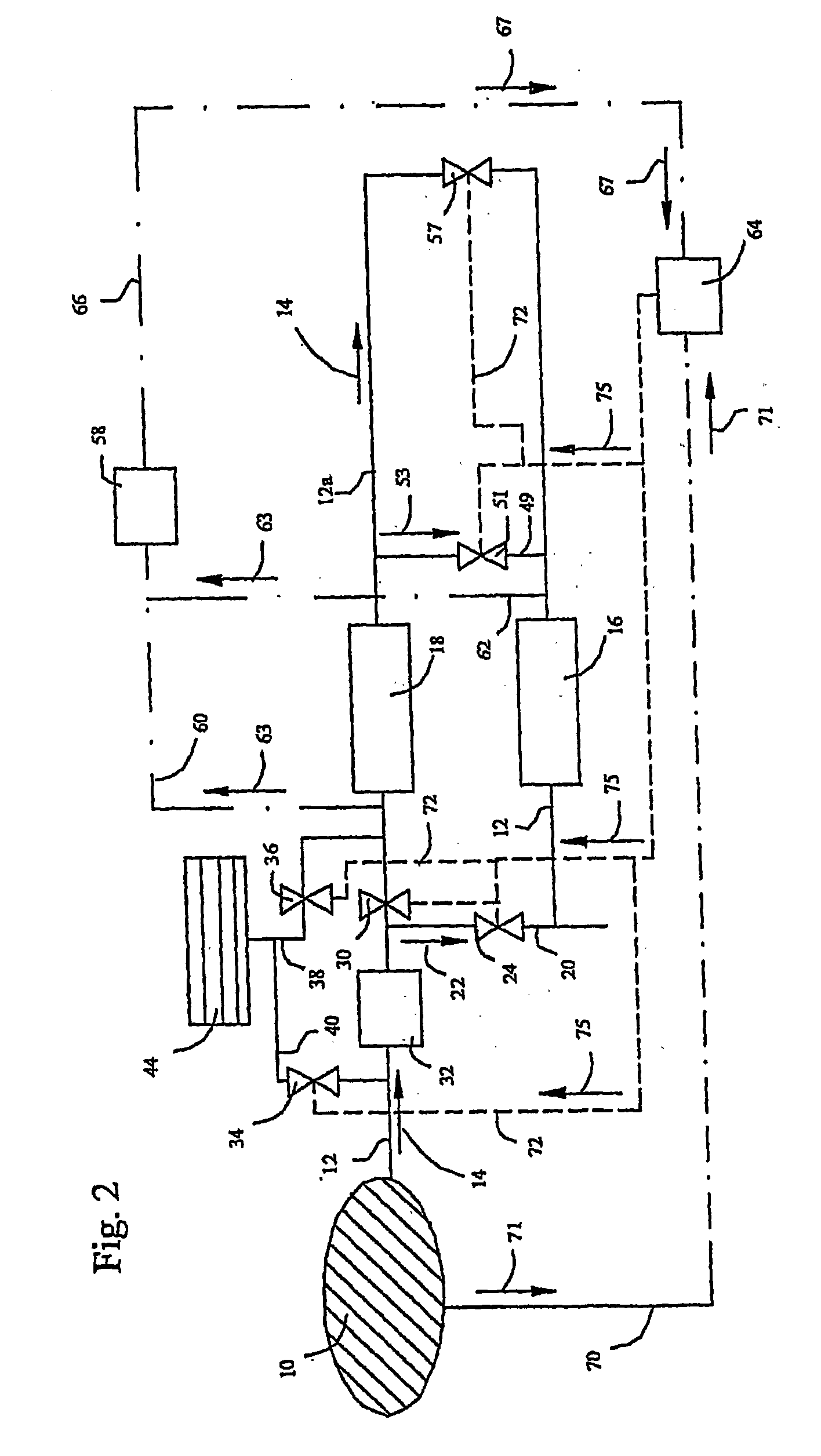

Image

  • Management of thermal fluctuations in lean NOx adsorber aftertreatment systems
  • Management of thermal fluctuations in lean NOx adsorber aftertreatment systems
  • Management of thermal fluctuations in lean NOx adsorber aftertreatment systems

Examples


second embodiment

[0066]FIG. 3 shows an aftertreatment system according to the present technique. As in the embodiment shown in FIG. 2, exhaust gas is directed, as indicated by arrow 14, to LNA 16 from engine block 10 through exhaust lines that include lead line 12 and hot line 86. A reductant can be introduced into lead line 12 through line 38 as controlled by valve 36 from store 44. Catalyst 18 is available downstream of the junction of line 38 and lead line 12 to allow for the exhaust gas to be heated and oxidized across catalyst 18 as needed. Exhaust gas temperature is further controlled by turbine-driven blower 82 disposed in lead line 12. Blower 82 accepts exhaust gas, expands and cools the gas to extract energy from the gas, and uses that energy to direct air through line 84 and valve 80 as indicated by arrow 94 (in the embodiment shown) to lead line 12 downstream of turbine-driven blower 82 and upstream of LNA 16.

[0067] The exhaust line includes hot line 86. Flow through hot line 86 is contro...

first embodiment

[0115] Controls, as described above, can also be employed to control embodiments having a turbine-driven blower 82. Here, however, control is needed to monitor the flow of air into lead line 12 through valve 80 during adsorption cycles. During a regeneration or de-sulfation cycle, valve 90 can be opened to direct all or a portion of the flow around turbine driven blower 82, as desired to match the temperature requirement for exhaust gas through LNA 16. Although, not shown in this embodiment, as would be understood by persons skilled in the technology involved here, a bypass could also be employed between catalyst 18 and LNA 16 (upstream of catalyst 18 and downstream of LNA 16). This bypass would be employed in the same manner as described for the first embodiment in FIG. 1.

[0116] In addition to hot line 86, line 91 could also be employed to remove load from turbine driven blower 82 when there is a need to maintain exhaust gas heat.

[0117] For the embodiment shown in FIG. 3 flow sens...


PUM


Abstract

A method and apparatus manage heat in exhaust gas in an aftertreatment system that employs a lean NOx adsorber. A de-sulfation hot line and cooling line are employed to control exhaust gas temperatures for adsorption, regeneration and de-sulfation cycles of the aftertreatment system where each cycle can require different chemical and exhaust gas temperatures independent of the engine operation. The method and apparatus include a SOx adsorber to provide greater system durability.

Description

CROSS-REFERENCE TO RELATED APPLICATION(S) [0001] This application is a continuation of International Application No. PCT / CA2004 / 000390, having an international filing date of Mar. 11, 2004, entitled “Management of Thermal Fluctuations in Lean NOx Adsorber Aftertreatment Systems”. International Application No. PCT / CA2004 / 000390 claimed priority benefits, in turn, from Canadian Patent Application No. 2,422,164 filed Mar. 14, 2003 and from Canadian Patent Application No. 2,453,689 filed Dec. 17, 2003. International Application No. PCT / CA2004 / 000390 is hereby incorporated by reference herein in its entirety.FIELD OF THE INVENTION [0002] This invention relates to methods and apparatuses for managing exhaust gas heat over the range of operating conditions required by a lean NOx adsorber aftertreatment system. BACKGROUND OF THE INVENTION [0003] Emissions controls for internal combustion engines are becoming increasingly important in transportation and energy applications. Oxides of nitroge...

Claims


Application Information

Patent Timeline
Patent Type & Authority Applications(United States)
IPC IPC(8): F01N3/00F01N3/10B01D53/94B01D53/96F01N3/02F01N3/04F01N3/05F01N3/08F01N3/20F01N3/32F01N5/04F01N13/02F02B37/00F02M25/07
CPCB01D53/9454F01N13/009F01N3/02F01N3/0205F01N3/043F01N3/05F01N3/0807F01N3/0814F01N3/0842F01N3/085F01N3/0871F01N3/0878F01N3/0885F01N3/2006F01N3/2046F01N3/2093F01N3/32F01N3/323F01N5/04F01N2240/02F01N2240/30F01N2270/02F01N2430/085F01N2570/04F01N2570/14F01N2610/03F01N2610/04F02B37/00F02M25/0718Y02C20/10Y02T10/22B01D53/96F02M26/15Y02T10/12Y02A50/20
Inventor ANCIMER, RICHARDHARRIS, JONATHAN M.S.LEBASTARD, OLIVIERDUNN, MARK E.
Owner WESTPORT POWER
Why Eureka
Try Eureka