Plastic gear

a technology of plastic gears and teeth, applied in the direction of gearings, gearing elements, toothed gearings, etc., can solve the problems of difficult to form a molded plastic gear with a high degree of accuracy, and achieve the effect of not deteriorating the shape and dimensional accuracy enhancing the transferability of the teeth part, and increasing the injection pressur

Inactive Publication Date: 2006-03-16
NISSHIN KOKI KK
View PDF4 Cites 16 Cited by
  • Summary
  • Abstract
  • Description
  • Claims
  • Application Information

AI Technical Summary

Benefits of technology

[0011] In order to achieve the above object and advantage, according to an embodiment of the present invention, there is provided a plastic gear including a teeth part which formed on its outer periphery, a web which is formed on the inner side of the teeth part, and a plurality of ring-shaped rims which is concentrically formed such that the web is divided into a plurality of ring-shaped webs in a concentrically circular shape. The plurality of ring-shaped webs includes two or more ring-shaped webs without rib which has no ribs for connecting adjacent ring-shaped rims on an outer peripheral side other than the ring-shaped web to which gates for resin molding are disposed at the time of resin molding.
[0012] In accordance with an embodiment of the present invention, gates for resin molding are disposed on an inner peripheral side and kept away from the teeth part when a plastic gear is resin molded. Therefore, a large difference of injection pressures is not generated between a portion near the gate and a portion far away from the gate in the teeth part. Accordingly, variation does not occur in the transferability to the teeth part. Further, when the gates are disposed on the inner peripheral side, the transferability in the teeth part is required to be enhanced by increasing the injection pressure. Even in this case, according to an embodiment of the present invention, two or more ring-shaped webs without rib are disposed on an outer peripheral side of the ring-shaped web to which the gates are disposed. Therefore, even when the ribs are formed on other ring-shaped webs, the ribs do not affect the shape and the dimensional accuracy of the teeth part. Alternatively, also in the case that all the ring-shaped webs are formed in a ring-shaped web without rib, the ribs do not affect the shape and the dimensional accuracy of the teeth part. As a result, for example, even when a large diameter of plastic gear with the diameter of 40 mm or more is produced, the accuracy of the first grade and the zero grade of the JGMA standard can be attained.
[0013] In accordance with an embodiment of the present invention, it is preferable that two or more ring-shaped webs without rib include an outermost peripheral ring-shaped web. According to the construction described above, molding sink due to the presence of the ribs does not occur on the teeth part at the time of resin molding.
[0014] In accordance with an embodiment of the present invention, the plurality of ring-shaped webs may include two or more ring-shaped webs without rib and at least a ring-shaped web with rib on which ribs are formed in the radial direction. In this case, it is preferable that the ring-shaped webs without rib and the ring-shaped web with rib are alternately disposed. According to the construction described above, the disturbance of the flow of the molten resin in the ring-shaped web with rib can be effectively reduced by the ring-shaped web without rib adjacent on the outer peripheral side. Further, when two or more ring-shaped webs with rib are disposed, it is preferable that the respective angular positions of ribs that are formed on one of the ring-shaped web with rib deviate from those of ribs that are formed on another of the ring-shaped web with rib. According to the construction described above, the shrinkage of resin in the ribs is not concentrated on specified positions in the circumferential direction and thus the shape and the dimensional accuracy of the teeth part are not deteriorated by the effects of the ribs.
[0015] In accordance with an embodiment of the present invention, all the plurality of ring-shaped webs may be ring-shaped webs without rib.
[0016] In accordance with an embodiment of the present invention, the gates for resin molding are preferably disposed to an innermost peripheral ring-shaped web.

Problems solved by technology

Consequently, it is very difficult for a molded plastic gear to be formed with a high degree of accuracy such as the first grade or the zero grade of the Japanese gear industrial standard (JGMA standard).

Method used


Image

  • Plastic gear
  • Plastic gear
  • Plastic gear

Examples


first embodiment

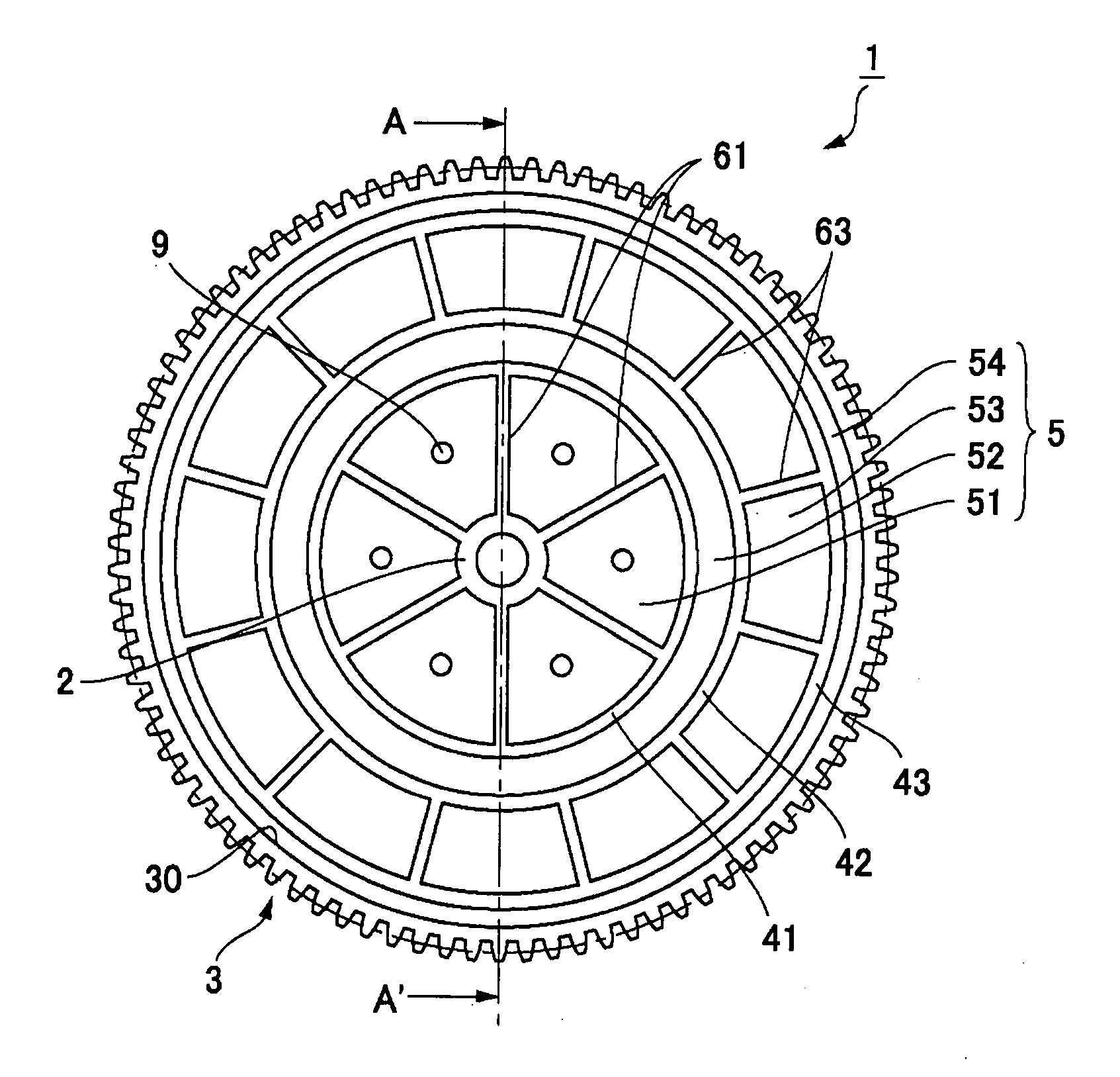
[0027] A plastic gear in accordance with a first embodiment of the present invention will be described below with reference to the accompanying drawings. FIG. 1(a) is a front view showing a molded plastic gear in accordance with the first embodiment of the present invention and FIG. 1(b) is a schematic cross-sectional view showing the portion that is cut by the line of A-A′ in FIG. 1(a).

[0028] As shown in FIGS. 1(a) and 1(b), a plastic gear 1 in the first embodiment of the present invention is used in office automation equipment such as a printer or a copying machine or in a precise driving system such as a window regulator for a car. The diameter of the plastic gear 1 is set to be large such as about 40 mm or more.

[0029] In the first embodiment of the present invention, the plastic gear 1 is provided with a cylindrical hub 2 at its center portion and a teeth part 3 on its outer peripheral portion. In the plastic gear 1, the inner side portion of a ring-shaped rim 30 near the toot...

second embodiment

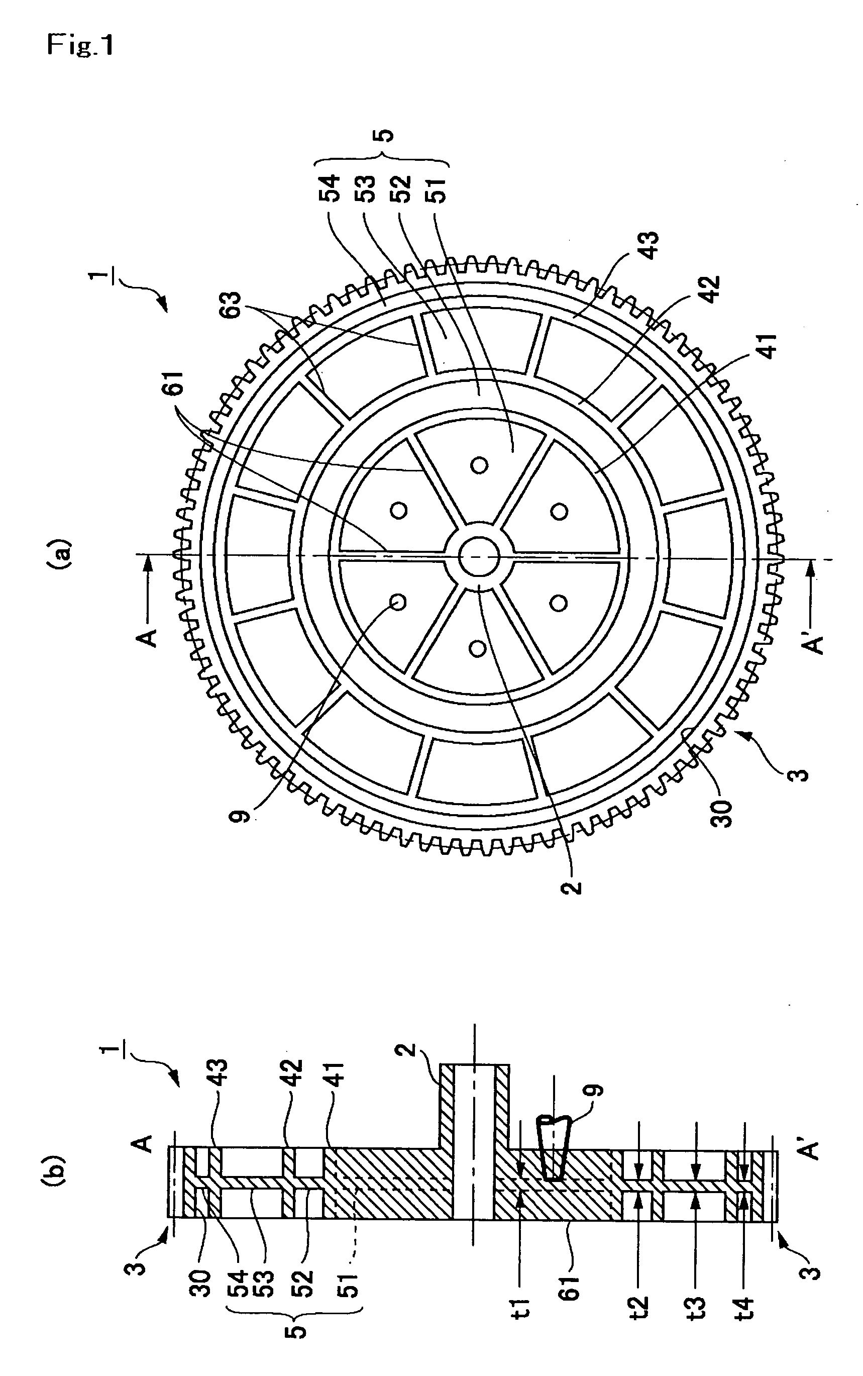
[0043]FIG. 2(a) is a front view showing a plastic gear in accordance with a second embodiment of the present invention and FIG. 2(b) is a schematic cross-sectional view showing the portion which is cut by the line of B-B′ in FIG. 2(a). The basic structures in the second embodiment and the third embodiment described later are similar to that in the first embodiment of the present invention. Therefore, the same notational symbols are used to the same portions providing the corresponding function and their descriptions are omitted.

[0044] As shown in FIGS. 2(a) and 2(b), similar to the first embodiment of the present invention, the plastic gear 1 in the second embodiment of the present invention is constructed such that the inside portion of the ring-shaped rim 30 near the tooth bottom portion is hollowed and a thin thickness web 5 is formed between the hub 2 and the teeth part 3. Five thick ring-shaped rims 41, 42, 43, 44, 45 which divide the web 5 into six ring-shaped webs 51, 52, 53...

third embodiment

[0055]FIG. 3(a) is a front view showing a molded plastic gear in accordance with a third embodiment of the present invention and FIG. 3(b) is a schematic cross-sectional view showing the portion which is cut by the line C-C′ in FIG. 3(a).

[0056] As shown in FIGS. 3(a) and 3(b), similar to the first and the second embodiments of the present invention, the plastic gear 1 in the third embodiment of the present invention is constructed such that the inside portion of the ring-shaped rim 30 near the tooth bottom portion is hollowed and a thin thickness web 5 is formed between the hub 2 and the teeth part 3. Five thick ring-shaped rims 41, 42, 43, 44, 45 which divide the web 5 into six ring-shaped webs 51, 52, 53, 54, 55, 56 formed in a concentrically circular shape are formed on the web 5 in a concentrical shape. All of six ring-shaped webs 51, 52, 53, 54, 55, 56 are formed as the ring-shaped web without rib which is provided with no rib on its both sides.

[0057] Also in the structure ac...


PUM


Abstract

A plastic gear includes a teeth part formed on its outer periphery, a web formed on the inner side of the teeth part and a plurality of ring-shaped rims concentrically formed such that the web is divided into a plurality of ring-shaped webs in a concentrically circular shape. The plurality of ring-shaped webs includes two or more ring-shaped webs without rib which has no ribs connecting adjacent ring-shaped rims on an outer peripheral side other than the ring-shaped web to which gates for resin molding are to be disposed at the time of resin molding.

Description

CROSS-REFERENCE TO RELATED APPLICATIONS [0001] This application claims priority to Japanese Application No. 2004-251423 filed Aug. 31, 2004, which is incorporated herein by reference. BACKGROUND OF THE INVENTION [0002] a) Field of the Invention [0003] The present invention relates to a plastic gear which is used in office automation equipment such as a printer or a copying machine or in a precise driving system such as a window regulator for a car. [0004] b) Description of the Related Art [0005] A molded plastic gear used in office automation equipment such as a printer or a copying machine or in a precise driving system such as a window regulator for a car is molded by injecting molten resin into a cavity of molding dies for injection molding from gates (see, for example, Japanese Patent Laid-Open No. Hei 10-278124). [0006] In such a plastic gear, a thin web 105 is formed on the inner side of a ring-shaped rim 130 near the bottom portion of a teeth part 103 formed on its outer peri...

Claims


Application Information

Patent Timeline
Patent Type & Authority Applications(United States)
IPC IPC(8): F16H1/14
CPCF16H55/06Y10T74/19688F16H2055/065
Inventor ASARI, TSUNEOEMORI, FUMIO
Owner NISSHIN KOKI KK
Why Eureka
Try Eureka