Toner, image forming apparatus, image forming method, and process cartridge

a technology of image forming apparatus and process cartridge, which is applied in the direction of electrographic process apparatus, electrographic process, instruments, etc., can solve the problems of insufficient low-temperature fixing property, energy-saving fixing property, and large so as to achieve excellent chargeability, transferability, and anti-spent property. , the effect of reducing the size of the entire image forming apparatus

Active Publication Date: 2009-04-23
RICOH KK
View PDF14 Cites 35 Cited by
  • Summary
  • Abstract
  • Description
  • Claims
  • Application Information

AI Technical Summary

Benefits of technology

[0035]Firstly, the present invention aims to provide an image forming apparatus, an image forming method and a process cartridge which are excellent in chargeability, anti-spent prop

Problems solved by technology

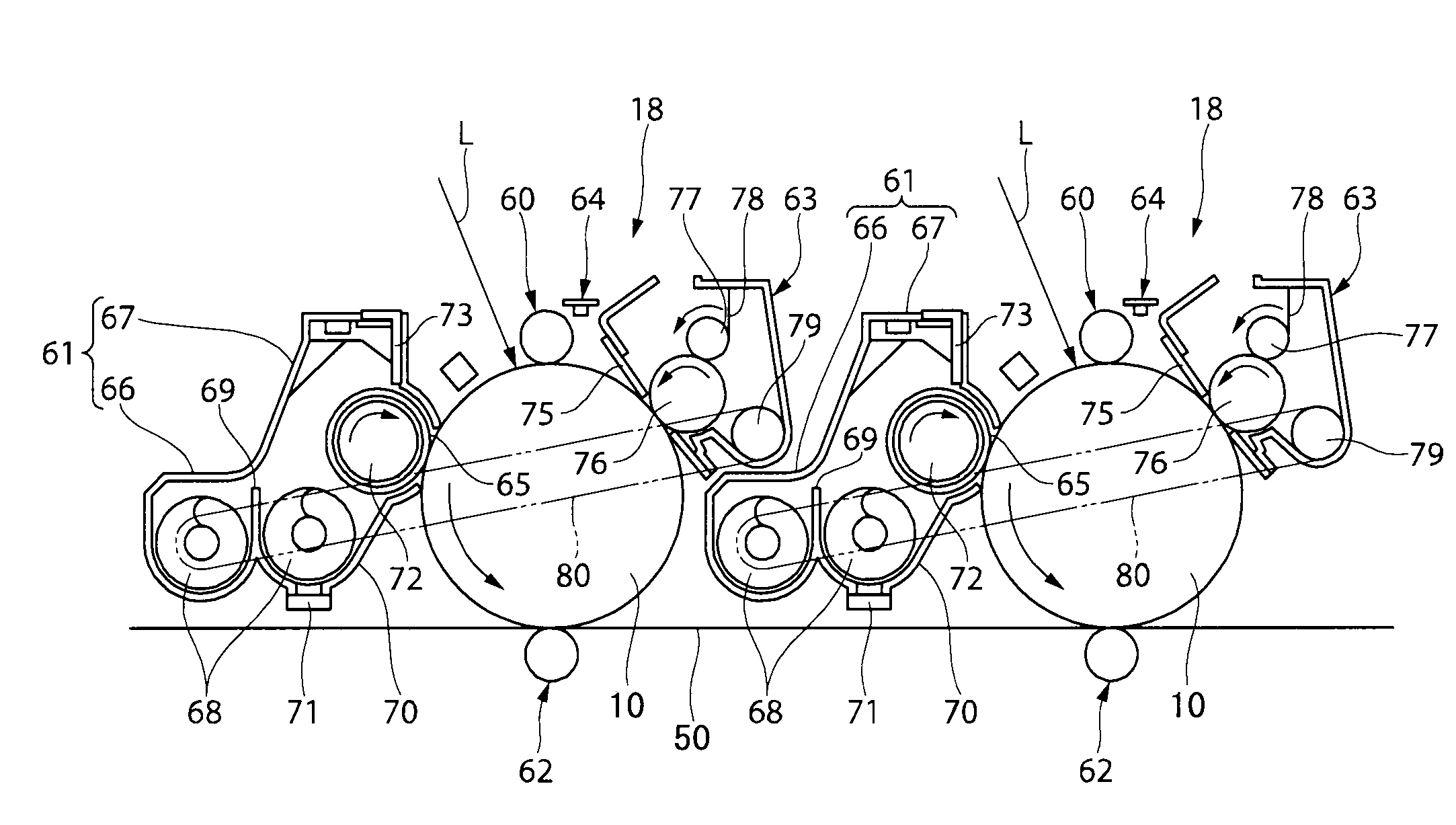
However, the tandem process has a disadvantage in that it requires arrangement of a plurality of image forming elements, and it results in large size of the entire image forming apparatus and high-costs.
However, with improved compactness and downsizing of image forming apparatuses, new problems have arisen, that is, each of units loaded in image forming elements needs to achieve high performance and drastically improved stability.
Such offset resistance can be improved by making a releasing agent exist on a surface of toner, however, when a not-specified toner is reused, not only the amount of a releasing agent residing on the toner surface may be reduced but also particles designed so as to have a core-shell structure with two or more layers may eccentrically exist on the toner surface, thereby the lower limit fixing temperature is inconveniently raised, causing insufficient low-temperature fixing property, i.e. energy saving fixing property.
In a low-temperature fixing system that is required to provide further lower-temperature fixing property, a fixing defect occurs due to inorganic fine particles which eccentrically exist on the toner surface, and the fixing temperature width cannot be ensured.
However, these rosin derivatives are low-molecular weight materials and are not chemically bonded to binder resins.
Therefore, a toner containing a large amount of a rosin derivative as a low-molecular weight material is likely to adhere onto a carrier in the case of a two-component developer and adhere onto a charge roller in the case of a one-component developer, and it is difficult to maintain the transferability and charge stability that have been obtained in the early stage of use.
However, these toners do not have a sufficient charge build-up property.
However, in these proposals, it is unfavorable in terms of environmental protection because the toners contain

Method used


Image

  • Toner, image forming apparatus, image forming method, and process cartridge
  • Toner, image forming apparatus, image forming method, and process cartridge
  • Toner, image forming apparatus, image forming method, and process cartridge

Examples


examples

[0560]Hereinafter, the present invention will be described in detail referring to specific Examples, however, the present invention is not limited to the disclosed Examples. On the contrary, the present invention is intended to cover various modifications and equivalent arrangements included within the spirit and scope of the appended claims.

[0561]In the following Synthesis Examples, Production Examples, Examples and Comparative Examples, physical property values of polyester resins and rosin compounds, and the weight average particle diameter of toners were measured according to the following methods.

[0562]

[0563](1) Preparation of Sample

[0564]Ten grams of resin was melted at 170° C. on a hot plate for 2 hours. Subsequently, the resin sample was naturally cooled for 1 hour in a state of being open to the atmospheric air at a temperature of 25° C. and a relative humidity of 50%. Thereafter, the resultant resin sample was pulverized by a coffee mill (National MK-61M) for 10 seconds.

[0...

synthesis example a1

[0589]—Synthesis of Acrylic Acid-Modified Rosin—

[0590]Into a 10 L flask equipped with a fractionating column, a reflux condenser, and a receiver, 5,630 g of an unpurified tall rosin and 610 g of acrylic acid were added, the mixture was heated to a temperature ranging from 160° C. to 210° C. in 2 hours, the mixture was reacted at 210° C. for 3 hours, and then distilled at 210° C. under a reduced pressure of 4 kPa, thereby a rosin modified with acrylic acid (acrylic acid-modified rosin) was synthesized.

[0591]The amount of an abietic acid contained in the unpurified tall rosin which had been used in production of the thus obtained acrylic acid-modified rosin, was 35.9% by mass, and the amount of the abietic acid contained in the acrylic acid-modified rosin was 14.2% by mass.

synthesis example a2

[0592]—Synthesis of Itaconic Acid-Modified Rosin—

[0593]Into a 10 L flask equipped with a fractionating column, a reflux condenser, and a receiver, 5,630 g of an unpurified tall rosin which had been used in production of the acrylic acid-modified rosin, and 1,130 g of itaconic acid were added, the mixture was heated to a temperature ranging from 160° C. to 210° C. in 2 hours, the mixture was reacted at 210° C. for 3 hours, and then distilled at 210° C. under a reduced pressure of 4 kPa, thereby a rosin modified with itaconic acid (itaconic acid-modified rosin) was synthesized.

[0594]The amount of an abietic acid contained in the thus obtained itaconic acid-modified rosin was 4.1% by mass.


PUM

PropertyMeasurementUnit
Percent by massaaaaaaaaaa
Softening pointaaaaaaaaaa

Abstract

An image forming apparatus including: a latent electrostatic image bearing member, a charging unit, an exposing unit, a developing unit, a transfer unit, and a fixing unit, wherein the toner contains at least a binder resin and a colorant, the binder resin contains a polyester resin obtained by polycondensation of an alcohol component with a carboxylic acid component containing a rosin compound, the amount of the rosin compound contained in the carboxylic acid component is 5% by mass or more based on the total mass of the alcohol component and carboxylic acid component, and the amount of an abietic acid contained in the toner is 1% by mass or less.

Description

BACKGROUND OF THE INVENTION[0001]1. Field of the Invention[0002]The present invention relates to a toner to be used in electrophotographic apparatuses such as copiers, electrostatic printing appratuses, printers, facsimiles, and electrostatic recording apparatuses, also relates to an image forming apparatuse, an image forming method, and a process cartridge.[0003]2. Description of the Related Art[0004]Conventionally, there have been known various image forming methods by electrophotographic process. Generally, a latent electrostatic image is formed by charging a surface of a latent electrostatic image bearing member (otherwise referred to as “photoconductor”, “electrophotographic photoconductor”, or “image bearing member”) and exposing the charged surface of the latent electrostatic image bearing member. Subsequently, the latent electrostatic image is developed using a toner to form a visible image on the latent electrostatic image bearing member. The visible image is directly trans...

Claims


Application Information

Patent Timeline
IPC IPC(8): G03G15/08G03G9/09G03G9/087
CPCG03G9/08711G03G9/08755G03G9/09783G03G9/08782G03G9/08775
Inventor NAKAYAMA, SHINYAKOTSUGAI, AKIHIROSABU, AKIYOSHI
Owner RICOH KK
Why Eureka
Try Eureka