Variable angle miter box

a technology of miter box and variable angle, which is applied in the field of variable angle miter box, can solve the problems of long time-consuming and labor-intensive, crown molding, ceiling, and difficult to accurately cut angles involving complex angles, and achieve the effect of accurately duplicate any angle and minimal effor

Inactive Publication Date: 2006-03-16
UNIWILL COMPUTAR +1
View PDF21 Cites 17 Cited by
  • Summary
  • Abstract
  • Description
  • Claims
  • Application Information

AI Technical Summary

Benefits of technology

[0011] An advantage of the present invention is the ability to accurately duplicate any angle with minimal effort.
[0012] These and other advantages, as will be realized, are provided in an adjustable miter box. The adjustable miter box has a planar base plate with a rear edge and a front edge. A blade kerf extends from the rear edge toward the front edge. A first guide plate is pivotally attached to the base plate. A second guide plate is pivotally attached to the base plate wherein the blade kerf extends between the first guide plate and the second guide plate. Each of the first guide plate and the second guide plate has a fixed fence and an adjustable fence wherein the adjustable fence is slidably attached to the guide plate such that the distance between the fixed fence and the adjustab

Problems solved by technology

Cuts involving complex angles, such as those required with crown molding, have long been considered difficult in the art.
Crown molding, typically placed on the diagonal between a wall and a ceiling, is particularly difficult to cut correctly.
The difficulty is exasperated by the fact that walls are rarely perpendicular with each other or with the ceiling.
The problem is difficult enough when right angles between walls and ceilings are attempted.
When purposefully odd, or non-perpendicular, angles are encountered the difficul

Method used


Image

  • Variable angle miter box
  • Variable angle miter box
  • Variable angle miter box

Examples


Embodiment Construction

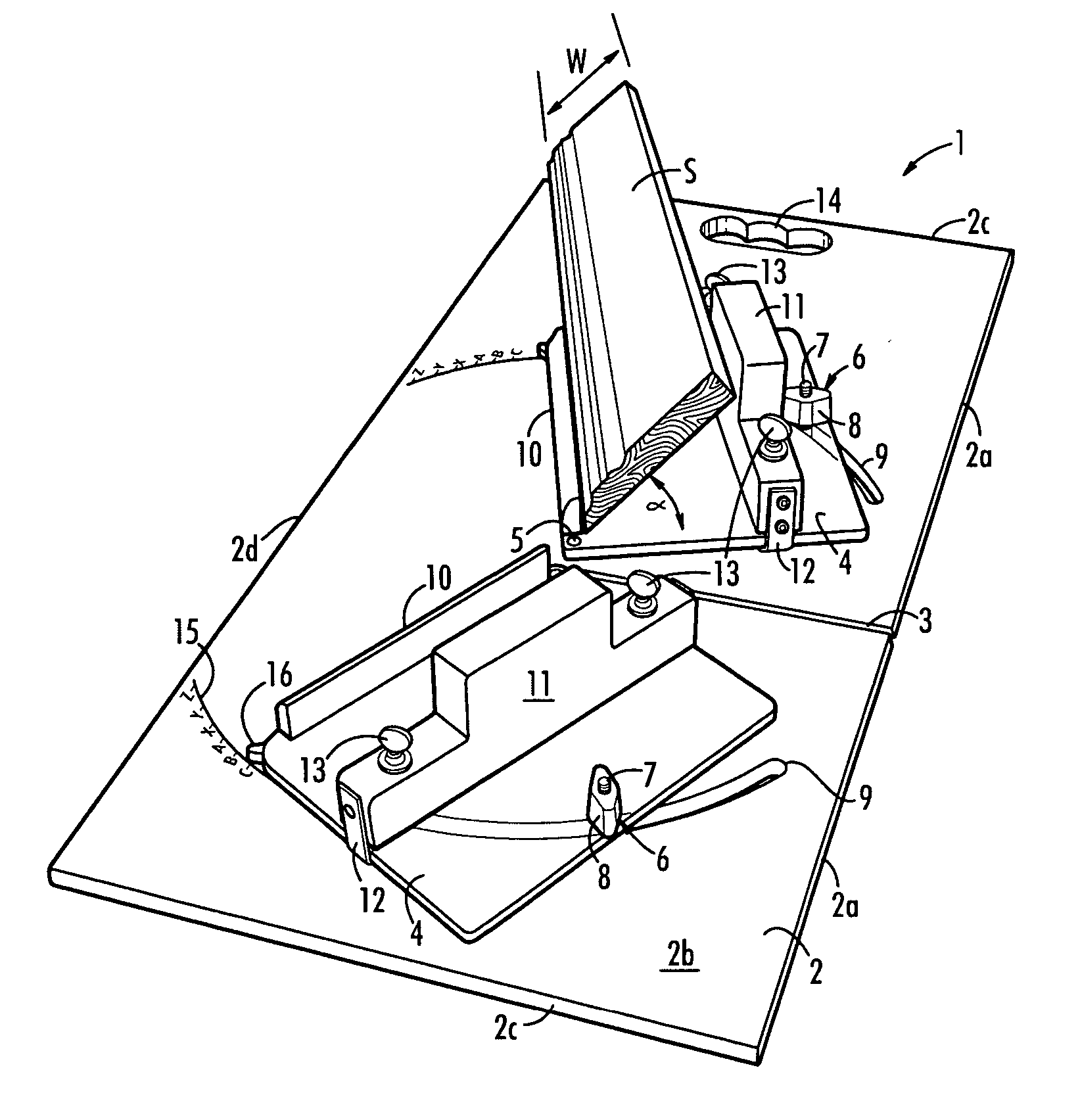
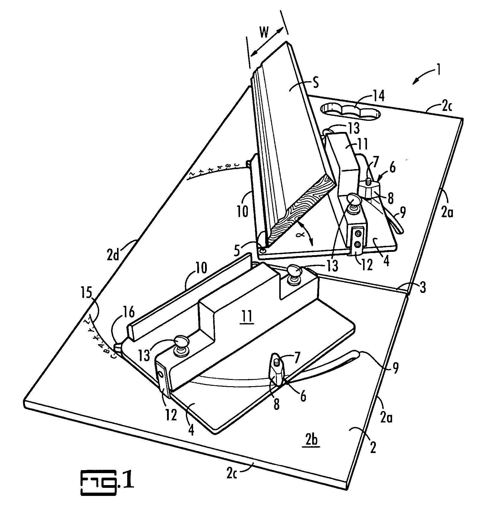
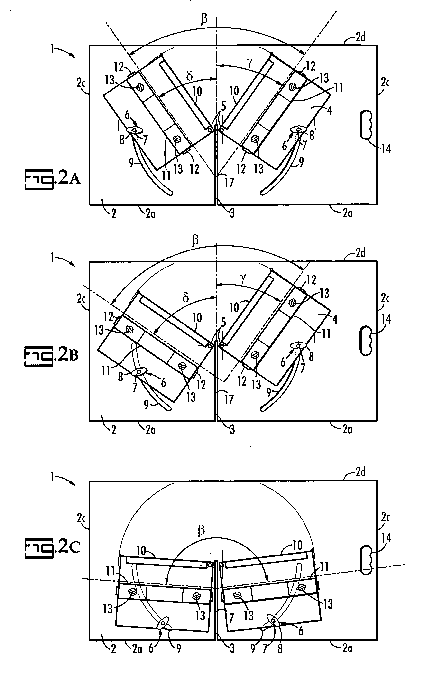
[0017] The present invention is specific to an adjustable miter box easily adapatable for use with a radial arm or miter saw and capable of repeatably securing stock for cutting of complex angles. The invention will be described with reference to the various figures which form an integral part of the specification. In the various figures similar elements will be numbered accordingly.

[0018] In the Figures, the adjustable miter box, generally represented at 1, comprises a base plate, 2, with a rear edge, 2a, face, 2b, side edges, 2c, and front edge, 2d. The rear edge, 2a, is preferably substantially linear from side edge to side edge to facilitate aligning the device with an existing fence on a radial arm or miter saw as would be realized by one of skill in the art. The base plate, 2, comprises a single blade kerf, 3, preferably perpendicular to the rear edge, 2a, and extending from the rear edge towards the front edge and between the pivots, 5. In operation the blade of the saw woul...


PUM

PropertyMeasurementUnit
Angleaaaaaaaaaa
Distanceaaaaaaaaaa

Abstract

An adjustable miter box with a base plate comprising a blade kerf. A first guide plate is pivotally attached to the base plate. A second guide plate is pivotally attached to the base plate wherein the blade kerf extends between the first guide plate and the second guide plate. Each guide plate guide plate has a fixed fence and an adjustable fence wherein the adjustable fence is slidably attached to the guide plate such that the distance between the fixed fence and the adjustable fence is adjustable and wherein the fixed fence and the adjustable fence remain parallel.

Description

BACKGROUND OF THE INVENTION [0001] The present invention is directed to a variable angle miter box. More specifically, the present invention is directed to a variable angle miter box capable of insuring accurate cuts on complex angles particularly with a radial arm saw or miter saw. [0002] Cuts involving complex angles, such as those required with crown molding, have long been considered difficult in the art. Crown molding, typically placed on the diagonal between a wall and a ceiling, is particularly difficult to cut correctly. The difficulty is exasperated by the fact that walls are rarely perpendicular with each other or with the ceiling. At ceiling corners, for example, crown molding pieces must accurately meet in the corner yet the angle between mating walls and the angle between the ceiling and each wall varies at each construction site and at each corner. The problem is difficult enough when right angles between walls and ceilings are attempted. When purposefully odd, or non-...

Claims


Application Information

Patent Timeline
IPC IPC(8): B23D15/00
CPCB27G5/023Y10T83/6609Y10T83/762
Inventor WILLIAMS, DENNIS J.SHEIL, ROBERT J.
Owner UNIWILL COMPUTAR
Why Eureka
Try Eureka