[0003] The present invention having the features of claim 1 has the
advantage that a risk of injury due to the gap between the guard and the work piece or the table top can be ruled out, whereby effective, simple means for this were created.
[0004] Due to the fact that the gap is automatically closed when it forms, regardless of its size, safety is automatically ensured and the previous source of danger is automatically eliminated.
[0007] Due to the fact that the protective panel includes two elongated holes extending perpendicularly to the table top and functioning as guide channels for the parallel displacement of the protective panel relative to the side wall, each of the elongated holes being penetrated by a screw which is screwed into the side wall, the heads—or the like—of which overlap the protective panel, the protective panel is supported using simple means such that it is movable relative to the side wall and is prevented from accidentally coming loose from the guard; this also ensures a secure resting position on the work piece and / or the table top. This is due to the fact that, when the saw blade and / or guard are angularly displaced, the protective panel changes its angular position but not its height relative to the work piece or the table top and reliably keeps the gap closed. In the case of an
angular displacement with an increasing obtuse angle, the side wall on which the protective panel is mounted moves upward relative to the protective panel.
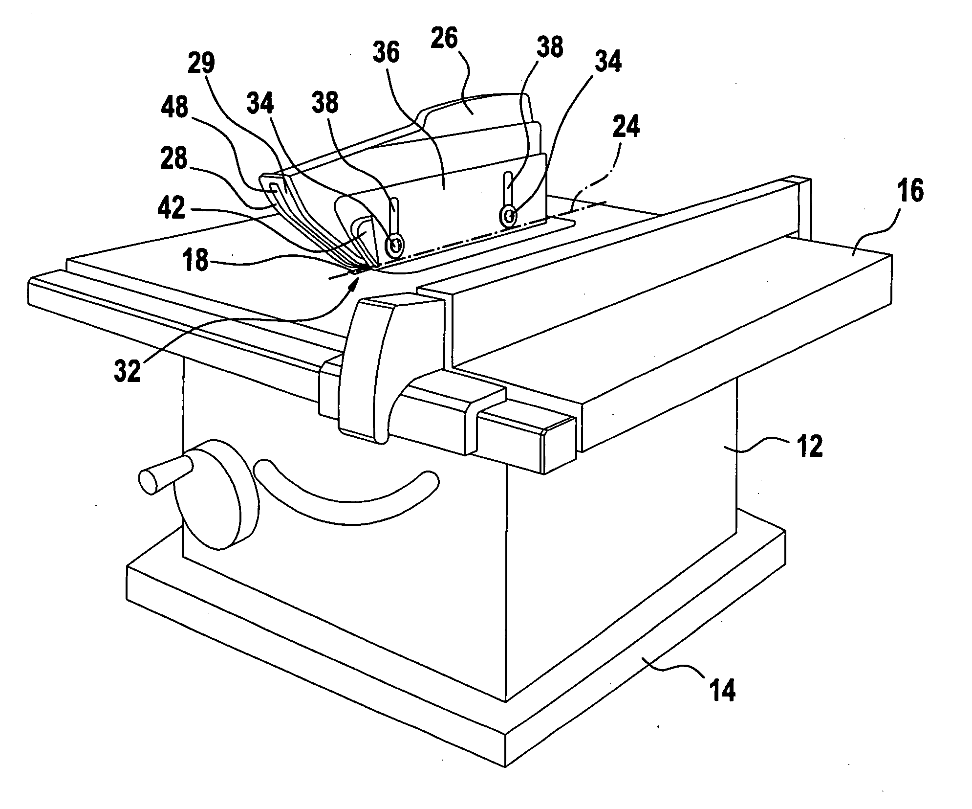
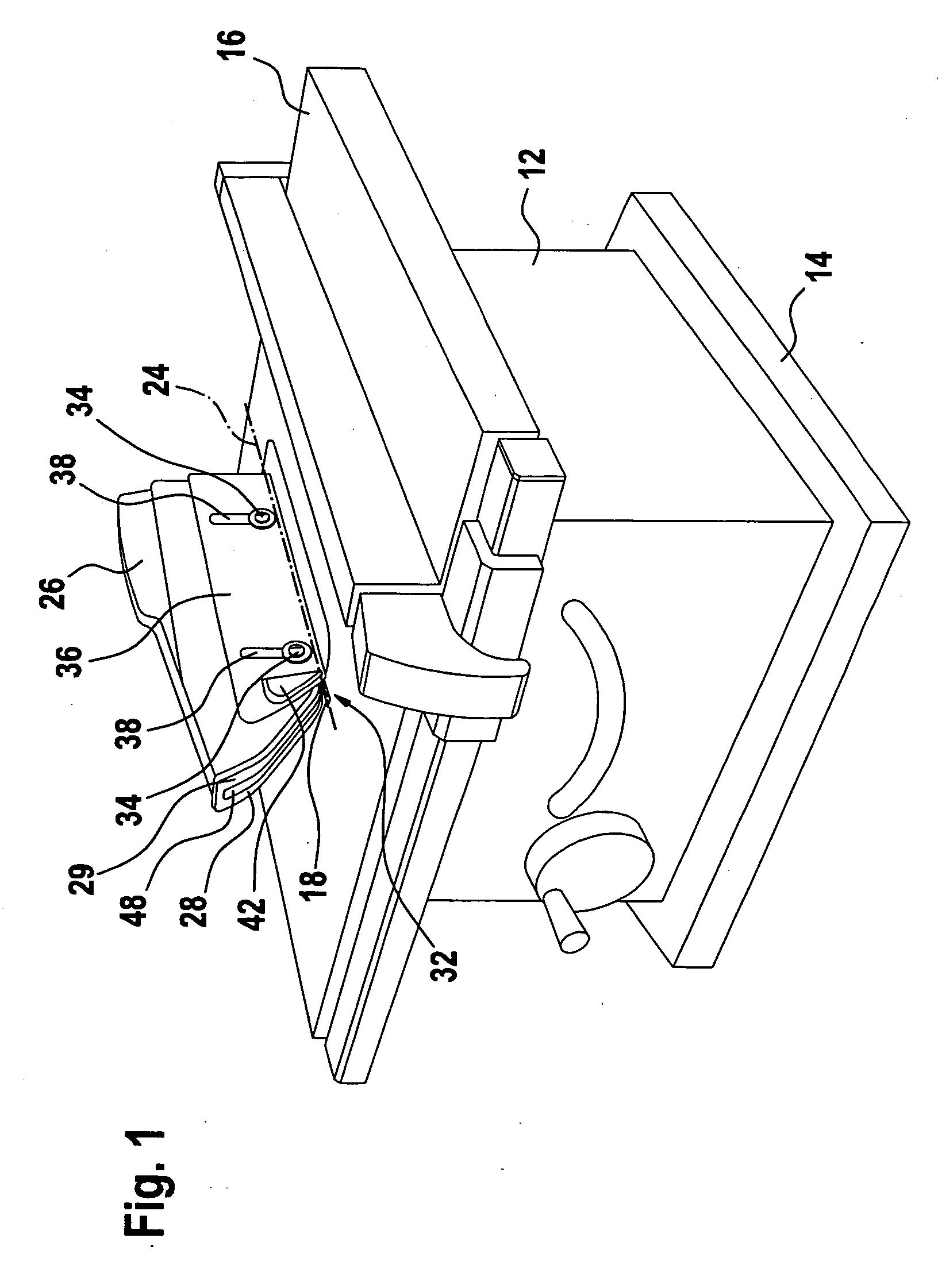
[0006] Due to the fact that the protective panel is supported on the side wall of the guard which forms an obtuse angle with the table top when the saw blade is swivelled, the safety-relevant side of the guard is automatically reliably protected.
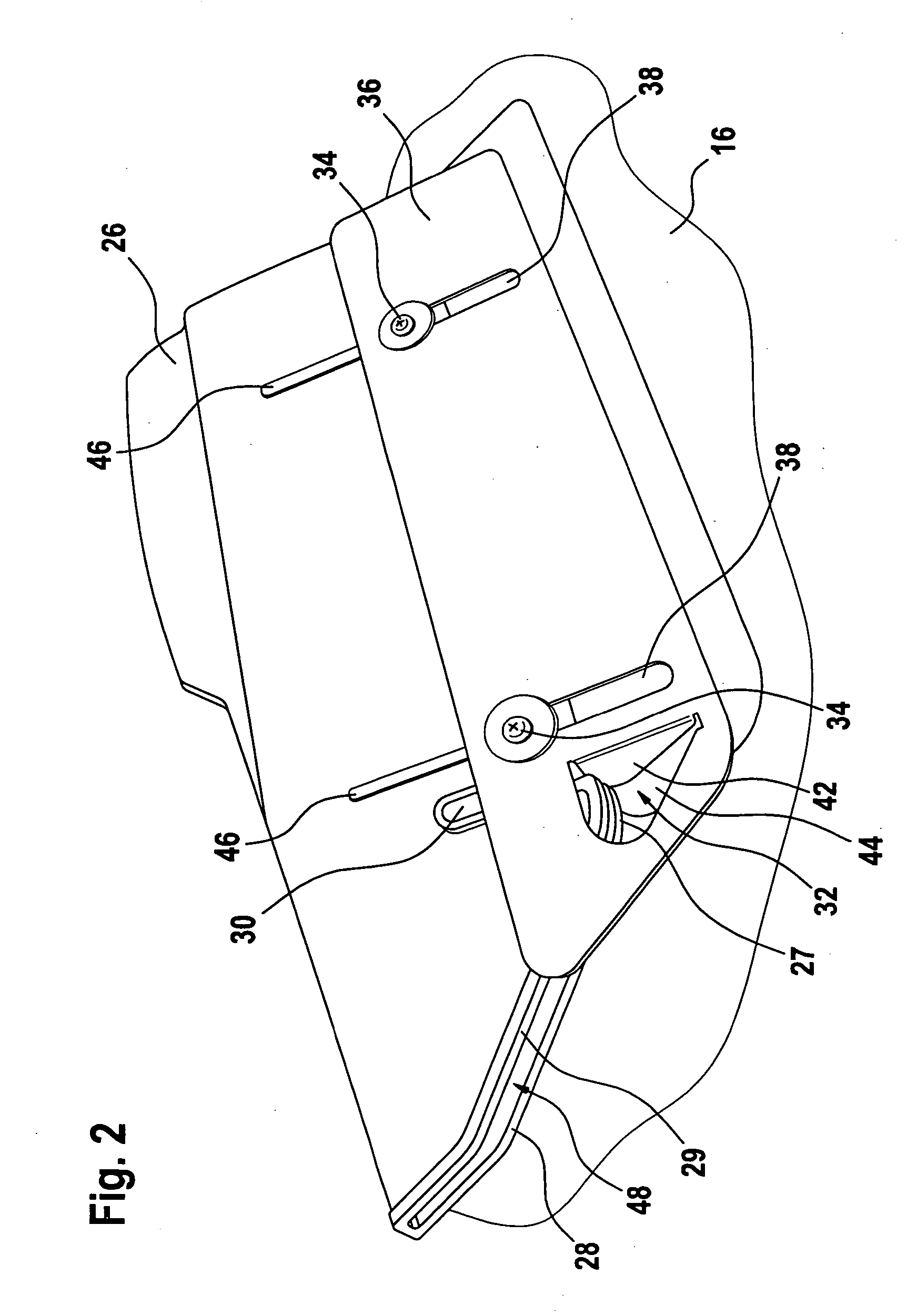
[0007] Due to the fact that the protective panel includes two elongated holes extending perpendicularly to the table top and functioning as guide channels for the parallel displacement of the protective panel relative to the side wall, each of the elongated holes being penetrated by a screw which is screwed into the side wall, the heads—or the like—of which overlap the protective panel, the protective panel is supported using simple means such that it is movable relative to the side wall and is prevented from accidentally coming loose from the guard; this also ensures a secure resting position on the work piece and / or the table top. This is due to the fact that, when the saw blade and / or guard are angularly displaced, the protective panel changes its angular position but not its height relative to the work piece or the table top and reliably keeps the gap closed. In the case of an
angular displacement with an increasing obtuse angle, the side wall on which the protective panel is mounted moves upward relative to the protective panel.
[0008] Due to the fact that, in the front region of the guard, an offset tab of the protective panel which is transverse to the protective panel and, therefore, transverse to the saw blade, extends in parallel with the elongated holes through a side wall of the guard to shortly before the diametrically opposed side wall, the region of the guard in front of the saw blade is also closed—except for the lateral gap between the side wall and the work piece—to prevent penetration by the hand.
[0007] Due to the fact that the protective panel includes two elongated holes extending perpendicularly to the table top and functioning as guide channels for the parallel displacement of the protective panel relative to the side wall, each of the elongated holes being penetrated by a screw which is screwed into the side wall, the heads—or the like—of which overlap the protective panel, the protective panel is supported using simple means such that it is movable relative to the side wall and is prevented from accidentally coming loose from the guard; this also ensures a secure resting position on the work piece and / or the table top. This is due to the fact that, when the saw blade and / or guard are angularly displaced, the protective panel changes its angular position but not its height relative to the work piece or the table top and reliably keeps the gap closed. In the case of an
angular displacement with an increasing obtuse angle, the side wall on which the protective panel is mounted moves upward relative to the protective panel.
[0010] Due to the fact that the side wall of the guard with the protective panel includes guide ribs on which the protective panel bears and is capable of gliding, friction between the protective panel and the side wall is minimized, and it is ensured that the two parts can move relative to each other in an unencumbered manner.
[0007] Due to the fact that the protective panel includes two elongated holes extending perpendicularly to the table top and functioning as guide channels for the parallel displacement of the protective panel relative to the side wall, each of the elongated holes being penetrated by a screw which is screwed into the side wall, the heads—or the like—of which overlap the protective panel, the protective panel is supported using simple means such that it is movable relative to the side wall and is prevented from accidentally coming loose from the guard; this also ensures a secure resting position on the work piece and / or the table top. This is due to the fact that, when the saw blade and / or guard are angularly displaced, the protective panel changes its angular position but not its height relative to the work piece or the table top and reliably keeps the gap closed. In the case of an angular displacement with an increasing obtuse angle, the side wall on which the protective panel is mounted moves upward relative to the protective panel.

