Eureka AIR delivers breakthrough ideas for toughest innovation challenges, trusted by R&D personnel around the world.

Variable area mass or area and mass species transfer device and method

a technology of species transfer and variable area mass, which is applied in the direction of indirect carbon-dioxide mitigation, combustion process, lighting and heating apparatus, etc., can solve the problems of inefficiency of species transfer device, long time-consuming and laborious, and course is at the expense of efficiency

Inactive Publication Date: 2006-03-16
WILSON SOLARPOWER CORP
View PDF9 Cites 39 Cited by
  • Summary
  • Abstract
  • Description
  • Claims
  • Application Information

AI Technical Summary

Benefits of technology

[0004] At least one actuator is disposed in operable communication with the species transfer masses, capable of selectively moving one or more of the masses indepen

Problems solved by technology

This of course is at the expense of efficiency.
Variable operation of machines also results in inefficiency with respect to the species transfer device.
The foregoing has long been a problem because all of the prior-art devices employ a fixed area or mass or area and mass ratio between elements being heated and those being cooled (or other transfer regime).
There is no capability within the prior art to change the area or mass or area and mass ratio of the species transfer device.

Method used


Image

  • Variable area mass or area and mass species transfer device and method
  • Variable area mass or area and mass species transfer device and method
  • Variable area mass or area and mass species transfer device and method

Examples


embodiment 10

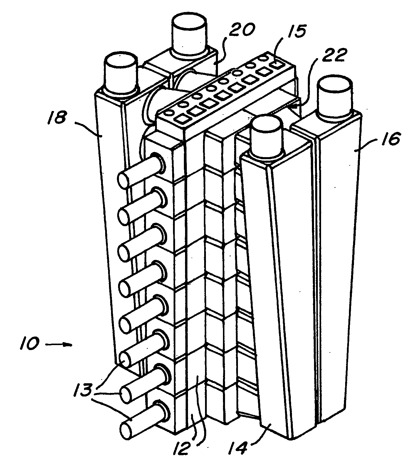
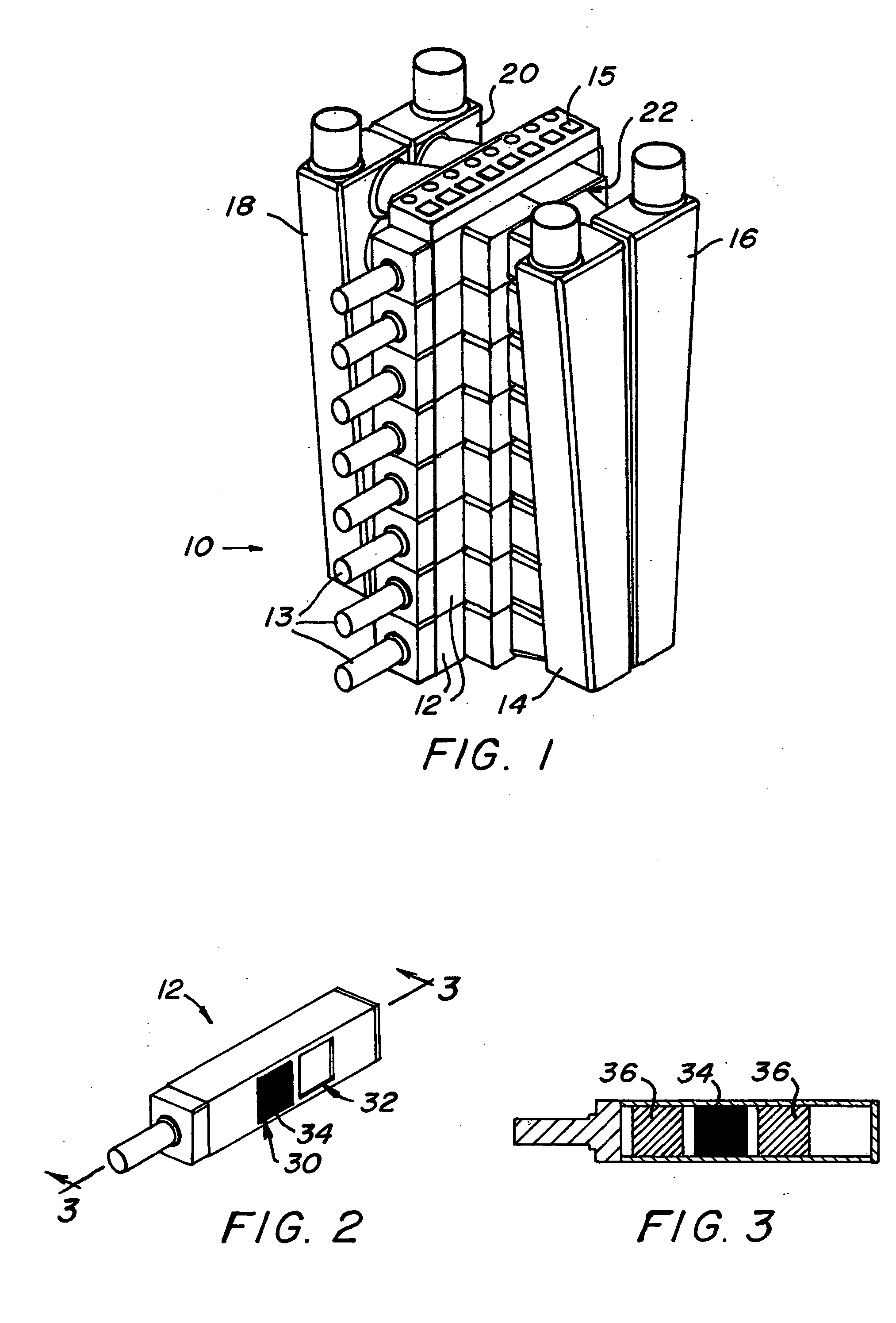
[0032] Referring to FIG. 1, a schematic perspective view of a first regenerator embodiment 10 is illustrated. The species transfer device 10 comprises a plurality of species transfer modules 12 (see FIG. 2 and FIG. 3). Modules 12 are actuatable by one or more actuators 13 (shown on each module 12 in this illustration but could be configured as one actuator to more of the modules at the expense of some variability or could be configured as more than one actuator for any module if desired) and controlled by a sequence-and-dwell controller 15 that determines the desired position of a particular module 12 and the period of time each particular mass should stay in a given fluid stream.

[0033] In fluid communication with the species transfer modules 12 are manifolds 14, 16, and 18 and 20. Manifolds 14 and 18 and manifolds 16 and 20 are in communication with each other through the intermediary of the species transfer modules 12. Each manifold pair is capable of conducting a fluid stream, an...

embodiment 210

[0047] Referring now to FIGS. 14, 15 and 16 a “rotary” species transfer device embodiment 210 exhibiting the properties of variability identified above is illustrated. For this device there are again four manifolds 214, 216, 218 and 220 wherein a first flow-stream passageway 230 is defined between manifolds 214 and 218 while a second flow-stream passageway 232 is defined between manifolds 216 and 220. In this example of the rotary species transfer device 210 four species transfer modules 212 are illustrated. Each module includes a rotor 242 comprising a species transfer mass 234 (see FIG. 15) rotatable about an axis of rotation, which brings the species transfer mass 234 into alignment with one or the other of passageways 230 or 232 or can be positioned out of alignment with either of these passageways (see FIG. 17) for blanking off a particular module 212.

[0048] Rotors 242 are driven by actuators 213, which comprise, in the illustrated embodiment, a motor 246 having a drive wheel 2...


PUM


Abstract

Disclosed herein is a-variable-area or mass or area and mass ratio species transfer device, one embodiment with a plurality of species transfer masses. At least one actuator is disposed in communication with the species transfer masses, capable of selectively moving one or more of the masses independently of other one or more of the masses into at least contact with a first fluid stream and into contact with a second fluid stream. Yet further disclosed herein is a method for controlling species transfer in a species transfer device. The method includes: selecting an appropriate mass / area ratio between a portion of a variable area or mass or area and mass ratio species transfer device exposed to a higher-temperature fluid and a portion of the species transfer device exposed to a lower-temperature fluid; exposing one selected portion of the species transfer device to the higher-temperature fluid; and exposing another selected portion of the species transfer device to the lower-temperature fluid.

Description

CROSS-REFERENCE TO RELATED APPLICATIONS [0001] This application claims the benefit of an earlier filing date from U.S. Provisional Application Ser. No. 60 / 546,583 filed Feb. 19, 2004, the entire contents of which is incorporated herein by reference.BACKGROUND [0002] Species transfer devices (e.g. regenerators, recuperators, etc.) are known to exist for many applications where recovery or transfer of species such as thermal energy is desirable. This includes applications employing turbines, fuel cells, other high-temperature machines and refrigeration type / low temperature machines as well. Traditionally, such species transfer devices have been custom designed for specific applications in order to operate at an optimum design point. Alternatively, a species transfer device designed for another application might be employed in a machine for which it was not designed to avoid cost (i.e. the custom-work cost) and where off-design-point operation is acceptable. This of course is at the ex...

Claims


Application Information

Patent Timeline
IPC IPC(8): F23L15/02F28D19/04F28F27/00
CPCF23L15/02F28F27/006F28D19/04Y02E20/34
Inventor MCRAY, RICHARD FERRISWILSON, DAVID GORDONKALLMEYER, JOERN KARSTEN
Owner WILSON SOLARPOWER CORP
Why Eureka
Eureka Blog
Learn More