Coiled tubing vibration systems and methods

a technology of vibration system and coiled tubing, which is applied in the direction of drilling casing, drilling pipe, borehole/well accessories, etc., can solve the problems of axial, lateral and/or rotational movement of the ct, undesirable vibration is often inherent in such systems, etc., and achieves the effect of reducing friction with the system, reducing the amount of wob, and accurate determination of weight-on-bit (“wob”) measurements

a technology of vibration system and coiled tubing, which is applied in the direction of drilling casing, drilling pipe, borehole/well accessories, etc., can solve the problems of axial, lateral and/or rotational movement of the ct, undesirable vibration is often inherent in such systems, etc., and achieves the effect of reducing friction with the system, reducing the amount of wob, and accurate determination of weight-on-bit (“wob”) measurements

US20060054315A1Inactive Publication Date: 2006-03-16COILED TUBING ENG SERVICES

Image

  • Coiled tubing vibration systems and methods
  • Coiled tubing vibration systems and methods
  • Coiled tubing vibration systems and methods

Examples


Embodiment Construction

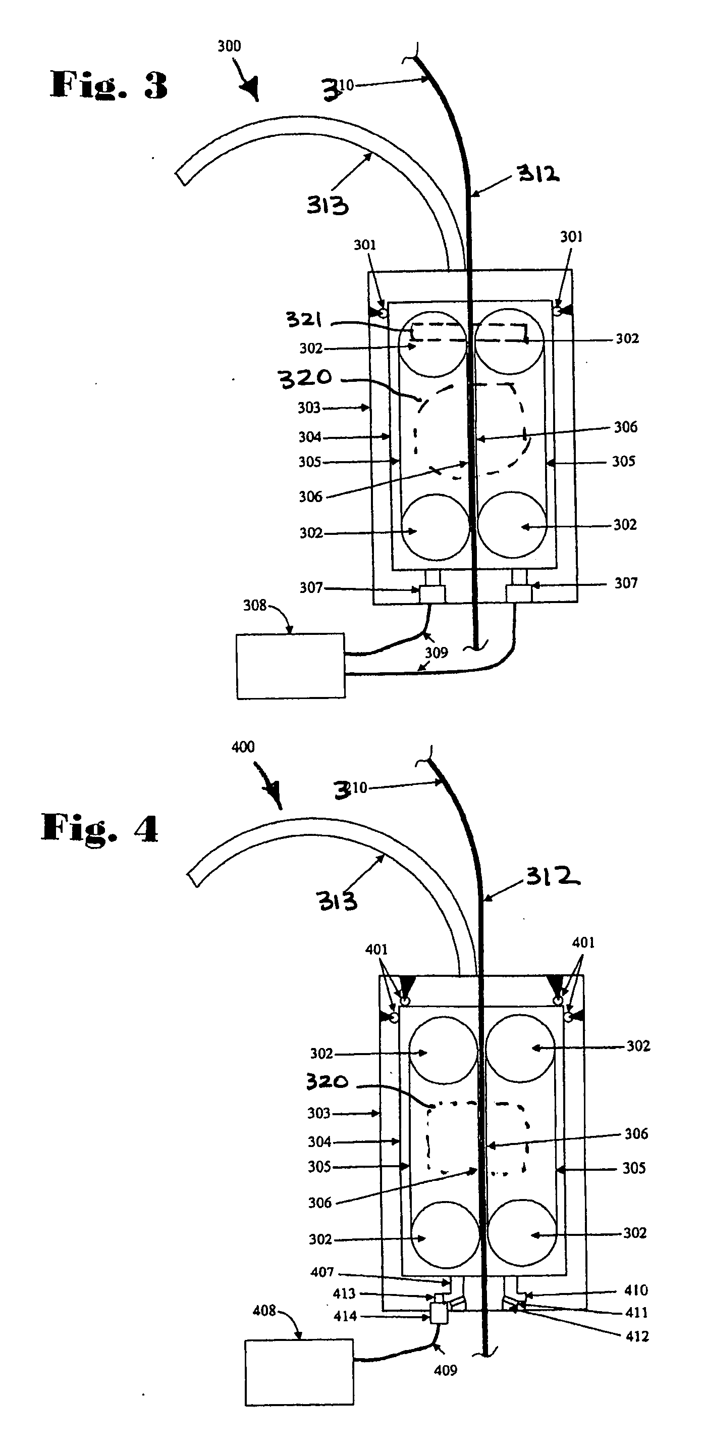
[0021] A system 300 according to the present invention as shown in FIG. 3 has a contra-rotating chain injector with vertical vibration capability. The injector. has an outer support frame 303 with an optional guide arch 313. Inside the support frame 303 there is a CT drive section 304 which contains two contra-rotating chains 305. These chains 305 pass around sprockets 302. The chains 305 are clamped against CT 312 throughout the length between the sprockets 302, this length shown as 306. A clamping system 321 is shown schematically. This clamping force holds the CT between the chains 305. The chains are then rotated by a drive system 320 (shown schematically) which turns the sprockets 302. One chain turns in one direction (clockwise or counter clockwise) and the other chain turns in the opposite direction (i.e., they are contra-rotating). As the chains turn, the CT 312 moves in our out of the well. A single or a plurality of hydraulic cylinders 307 provide vibration by moving the i...


PUM


Abstract

Systems and methods for vibrating coiled tubing as it is moved in an earth wellbore.

Description

BACKGROUND OF THE INVENTION [0001] 1. Field of the Invention [0002] The present invention is directed to coiled-tubing systems and methods. [0003] 2. Description of Related Art [0004] Coiled tubing (“CT”) systems are used to perform drilling or intervention operations (“coiled tubing operations” or “CTO”) in wells. FIG. 1 illustrates a prior art CT system 100 used for CTO. The CT 102 is stored on the reel 101. The CT 102 is run into the well 106 below the surface 108 by bending around a guide arch 103, passing through an injector 104 and a well control stack 105. A bottom-hole assembly (BHA) 107 is often attached to the end of the CT. The surface 108 may be ground level or a rig floor when on land. Offshore it may be the surface of the water or the floor of a rig or platform, or the sea floor. [0005]FIG. 2 illustrates a similar prior art CTO system 200. The CT 102 is pulled off of the storage reel 101 by a small injector 209. It then loops upwards through the air in what is known as...

Claims


Application Information

Patent Timeline
16 Mar 2006
Publication
US20060054315A1
IPC
E21B19/22
CPC
E21B28/00; E21B19/22
Inventors
NEWMAN, KENNETH R.