Acoustic fluid machine

a technology of acoustic fluid and acoustic pump, which is applied in the direction of machines/engines, refrigeration components, light and heating apparatus, etc., can solve the problems of inability to achieve the desired discharge pressure, complicated structure, and high cos

Inactive Publication Date: 2006-03-16
ANEST IWATA CORP
View PDF15 Cites 6 Cited by
  • Summary
  • Abstract
  • Description
  • Claims
  • Application Information

AI Technical Summary

Problems solved by technology

Thus, if the resonance frequency is out of the certain range, compression ratio becomes smaller to make it impossible to achieve desired discharge pressure.
So it is necessary to change the actuator for the piston using arithmetic machine, which makes its structure more complicate and expensive.

Method used


Image

  • Acoustic fluid machine
  • Acoustic fluid machine
  • Acoustic fluid machine

Examples


Embodiment Construction

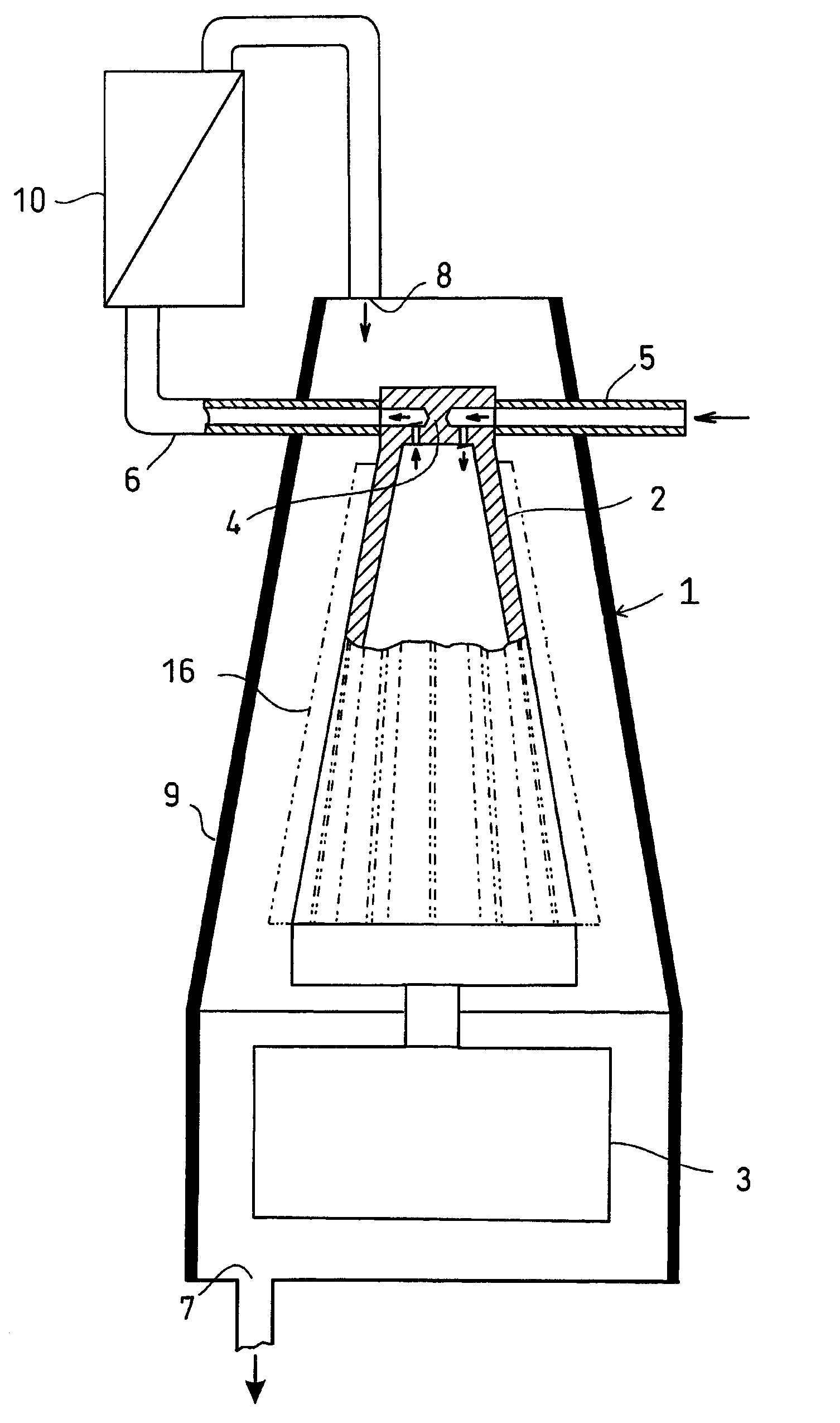
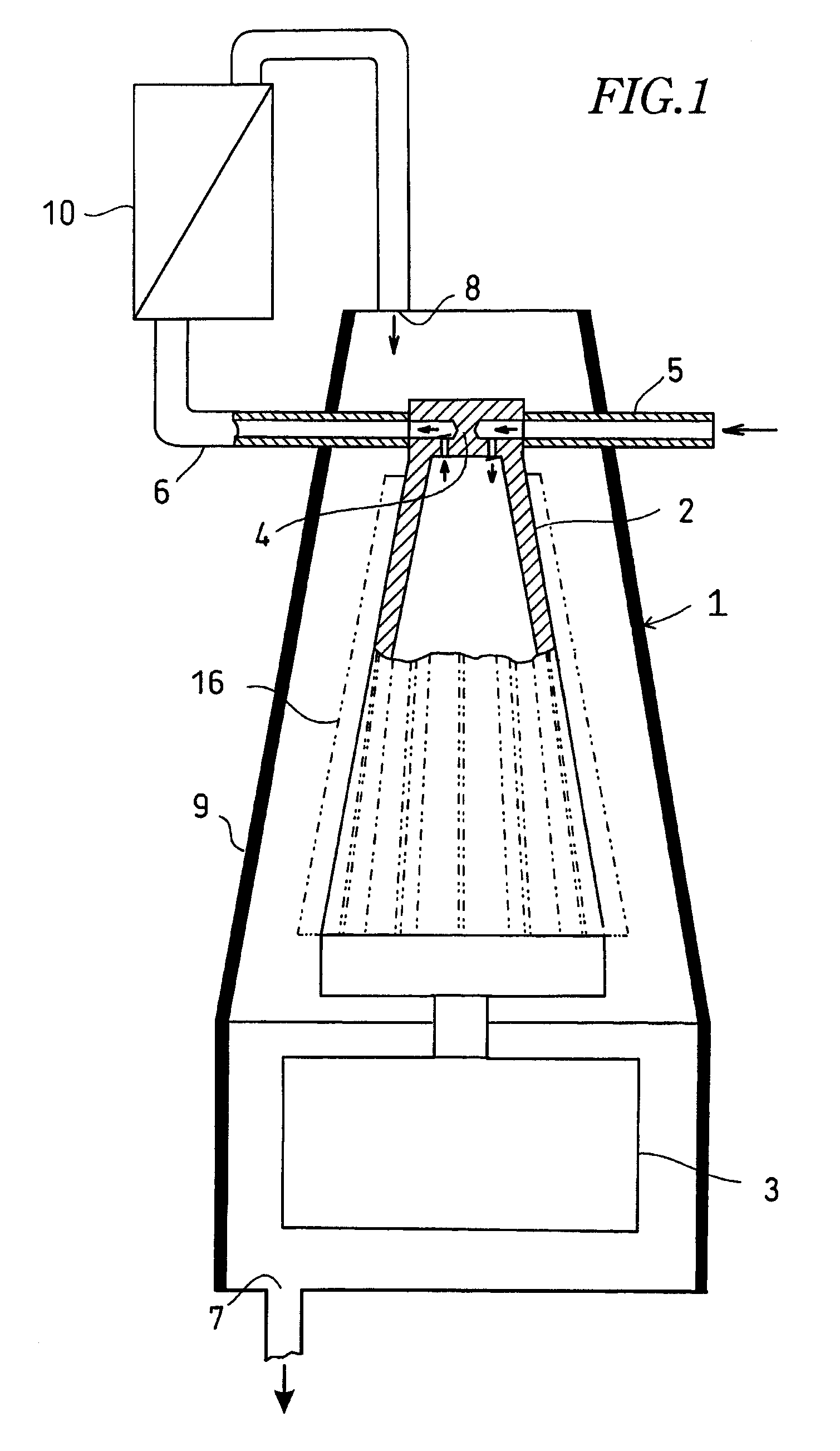
[0014] Numeral 1 denotes an acoustic fluid machine 1. In a larger-diameter base of an acoustic resonator 2, there is provided a piston (not shown) which reciprocates axially at high speed at very small amplitude. Owing to pressure fluctuation in the acoustic resonator 2 involved by reciprocal motion of the piston, air or other fluids are sucked from a sucking pipe 5 via a valve device 4 at the top end of the acoustic resonator 2, and discharged from a discharge pipe 6.

[0015] The acoustic resonator 2 is contained in a gas guide 9 having an outlet 7 at the base end and an inlet 8 at the top end with a gap.

[0016]FIG. 1 shows an embodiment in which the discharge pipe 6 of the valve device 4 is connected to the inlet 8 via an air conditioner 10 which cool air.

[0017] In FIG. 2, instead of the air conditioner 10 connected to the discharge pipe 6, cooling fins 11 are provided on the discharge pipe 6.

[0018] In FIG. 3, there is provided a dividing valve 12 on the discharge pipe 6 from the...


PUM


Abstract

A piston is reciprocated axially at high speed at very small amplitude by an actuator in the larger-diameter base of an acoustic resonator. According to pressure fluctuation in the acoustic resonator involved by reciprocal motion of the piston, fluid is sucked into and discharged from the acoustic resonator via a valve device at the top end of the acoustic resonator. The acoustic resonator is contained in a gas guide. Fluid from the valve device is introduced into the gas guide to cool the valve device.

Description

BACKGROUND OF THE INVENTION [0001] The present invention relates to an acoustic fluid machine which enables temperature gradient between a base having an actuator of acoustic resonator and the top end having a valve device for sucking and discharging fluid to be as small as possible. [0002] As disclosed in U.S. patent application Ser. No. 10 / 922,383 filed Aug. 19, 2004 corresponding to Japanese Patent Pub. No. 2004-116309, there is provided an actuator that has a piston is provided in the base of a tapered acoustic resonator for generating in-tube wave motion by acoustic resonance, and a valve device for sucking and discharging fluid according to pressure fluctuation therein. [0003] In the acoustic fluid machine, shape and size of the acoustic resonator are determined to generate the optimum resonance frequency when temperature of fluid is within a certain range. The optimum frequency renders the optimum sucking and discharging of fluid. Thus, if the resonance frequency is out of th...

Claims


Application Information

Patent Timeline
Patent Type & Authority Applications(United States)
IPC IPC(8): F01N1/14
CPCF04F7/00
Inventor KAWAHASHI, MASAAKIFUJIOKA, TAMOTSUHOSSAIN, MOHAMMED ANWARSAITO, MASAYUKI
Owner ANEST IWATA CORP
Why Eureka
Try Eureka