
Absolute angle detecting device

Inactive Publication Date: 2006-03-16
ALPS ALPINE CO LTD
View PDF11 Cites 3 Cited by
  • Summary
  • Abstract
  • Description
  • Claims
  • Application Information

AI Technical Summary

Benefits of technology

[0010] Accordingly, the invention has been made in view of the above problems, and it is an object of the invention to provide an absolute angle detecting device capable of simplifying an algorithm for signal processing, of performing signals processing at high speed, and of reducing the size of a signal processing circuit.

Problems solved by technology

However, as in the absolute angle detecting device disclosed in Japanese Unexamined Patent Application Publication No. 10-227631, when the absolute angle within one revolution is signal-processed on the basis of code signals output from the increment-type encoder, and when the rotation amount over one revolution is signal-processed on the basis of signals output from the absolute-type encoder, which is different from the code signals, an algorithm for signal processing is complicated, which makes it difficult to process signals at high speed.
In addition, in this case, a lot of signal processing circuits are needed, which makes it difficult to manufacture an absolute angle detecting device with low costs.

Method used


Image

  • Absolute angle detecting device
  • Absolute angle detecting device
  • Absolute angle detecting device

Examples


Embodiment Construction

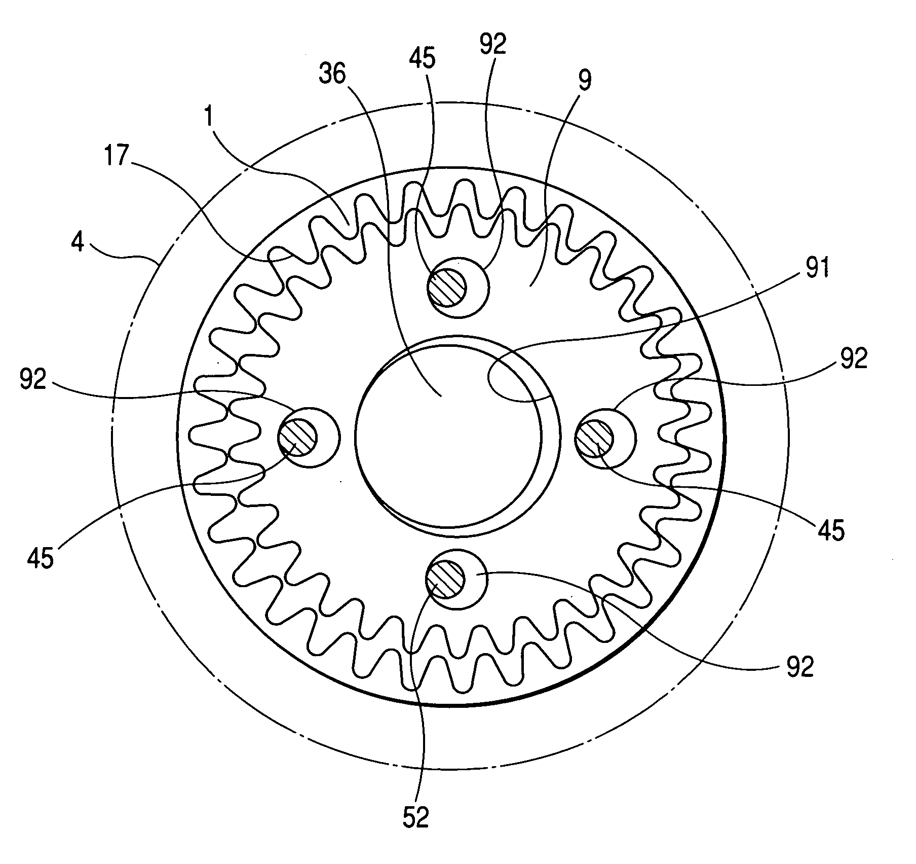
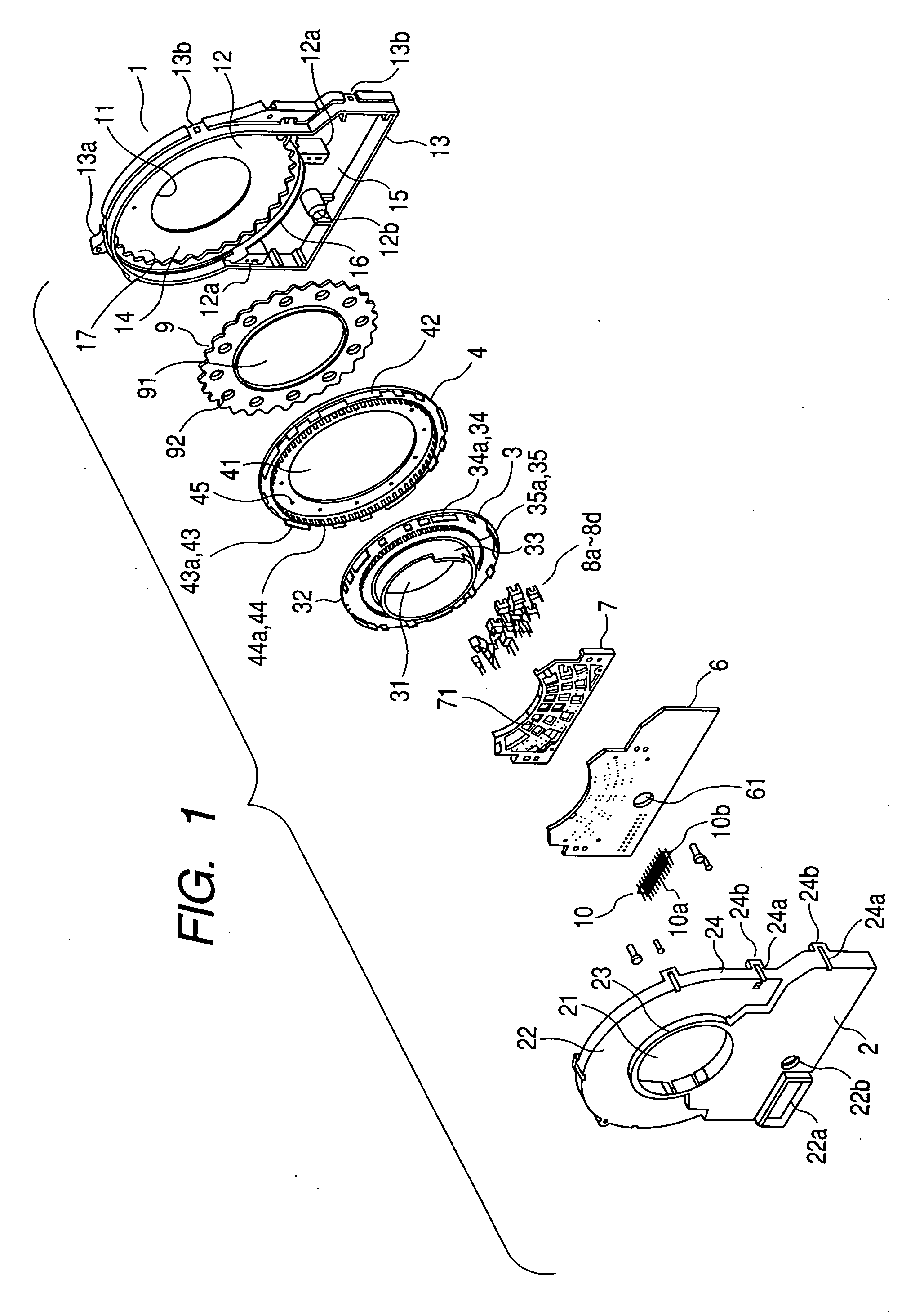
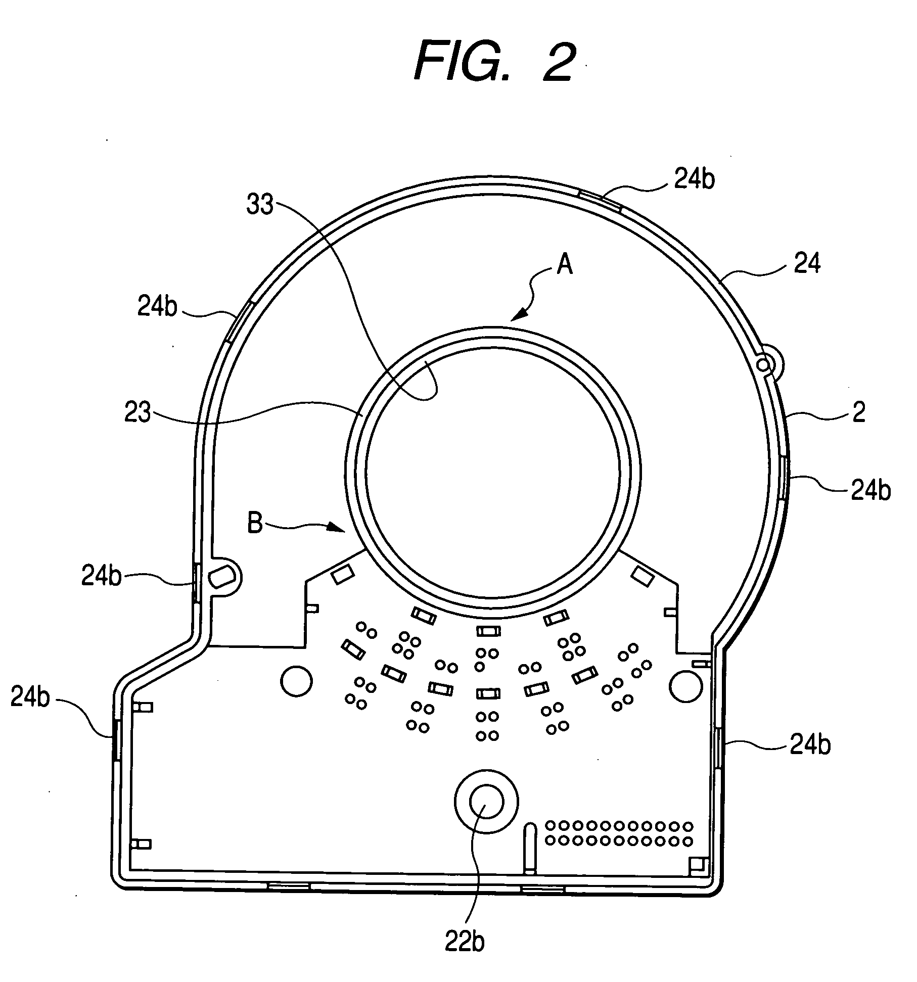
[0029] Hereinafter, a code wheel supporting structure of a rotation detecting device, which is an example of a rotary member supporting structure according to the invention, will be described with reference to FIGS. 1 to 8. FIG. 1 is an exploded perspective view of the rotation detecting device according to an embodiment of the invention. FIG. 2 is a view illustrating an inner side of a cover according to the embodiment. FIG. 3 is a view illustrating a rear side of a first code wheel according to the embodiment. FIG. 4 is a view illustrating an inner connection state of a planetary gear, an internal gear, and a second code wheel according to the embodiment. FIG. 5 is an explanatory diagram illustrating an assembly of the first code wheel, the second code wheel, and a signal detecting element group according to the embodiment. FIGS. 6 and 7 are tables illustrating gray-code patterns detected by the first code wheel according to the embodiment. FIG. 8 is a table illustrating a gray-co...


PUM


Abstract

First and second signal detecting element groups are respectively arranged to face first and second signal detecting tracks that are provided on a first code wheel. In addition, third and fourth signal detecting element groups are respectively arranged to face third and fourth signal detecting tracks that are provided on a second code wheel. A code string is output from the first and second signal detecting element groups to obtain a circular gray-code for detecting the rotation of the first code wheel within one revolution. Further, a code string is output from the third and fourth signal detecting element groups to obtain a circular gray-code for detecting the rotation of the first code wheel over one revolution.

Description

BACKGROUND OF THE INVENTION [0001] 1. Field of the Invention [0002] The present invention relates to an absolute angle detecting device applicable to, for example, a steering angle sensor of a car, and more particularly, to a device that allows a control device to easily process signals. [0003] 2. Description of the Related Art [0004] As the related art, there has been known a technique in which an absolute angle detecting device is provided between a steering shaft and a chassis of a car, and various control operations, such as the attenuation force control of a suspension, the shift position control of an automatic transmission, and the steering control of rear wheels of a car with four-wheel drive, are performed on the basis of, for example, the steering angle, steering speed, and steering direction of a steering wheel detected by the absolute angle detecting device. [0005] The steering wheel (steering shaft) is constructed so as to make one or more rotations whenever it shifts f...

Claims


Application Information

Patent Timeline
IPC IPC(8): G01D5/34
CPCG01D5/04G01D5/34776G01D5/34738G01D5/2492G01D5/249G01B21/22G01D5/245
Inventor SANO, TADASHI
Owner ALPS ALPINE CO LTD
Features
  • Generate Ideas
  • Intellectual Property
  • Life Sciences
  • Materials
  • Tech Scout
  • Unparalleled Data Quality
  • Higher Quality Content
  • 60% Fewer Hallucinations
Learn More