Self-adjusting lens mount for automated assembly of vehicle sensors

a technology for automatic assembly and vehicle sensors, applied in the field of vehicle mounted imaging systems, can solve the problems of less than ideal conditions, affecting the system's estimation of vehicle position, calibration and alignment of optical assemblies, including lenses and sensors

Inactive Publication Date: 2006-03-16
ITERIS INC +1
View PDF22 Cites 57 Cited by
  • Summary
  • Abstract
  • Description
  • Claims
  • Application Information

AI Technical Summary

Benefits of technology

[0011] In a first aspect the present invention provides a lens mount system, comprising a lens mount base and a lens holder. The lens mount base has a back side and a front side and the lens holder has a first end adapted to couple to the front side of the lens mount base and a second end with an opening for receiving a lens. The lens holder has an inner bore with a central axis extending from the opening, the inner bore having a first threaded portion. The lens holder inner bore further has a second unthreaded portion, and axial alignment means configured in the second portion of the inner bore for maintaining the lens aligned with the central axis during focusing adjustment along the axial direction.

Problems solved by technology

In particular, a misalignment of the lens relative to the imager could cause the road scene to be translated across the image which could affect the system's estimation of vehicle position.
Any deviation of these relationships will cause there to be less than ideal conditions for detecting the relevant features in the video image.
However, a common issue for on-board sensors is calibration and alignment of the optical assembly, including the lens and sensor.
Another source of misalignment that is problematic in conventional approaches to aligning lens assemblies in image processing applications is a translational misalignment of the lens optical axis across the imager array.

Method used


Image

  • Self-adjusting lens mount for automated assembly of vehicle sensors
  • Self-adjusting lens mount for automated assembly of vehicle sensors
  • Self-adjusting lens mount for automated assembly of vehicle sensors

Examples


Embodiment Construction

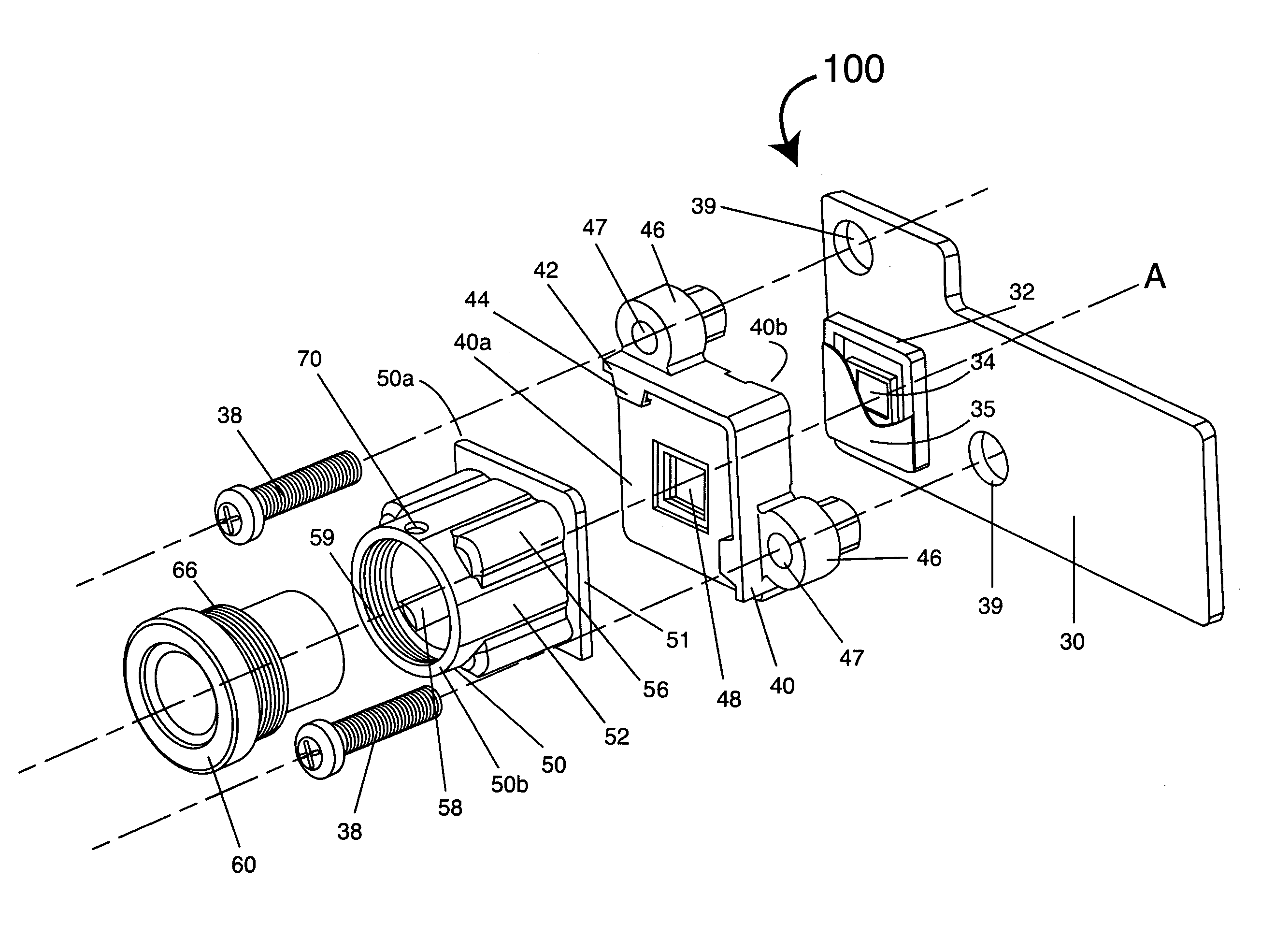
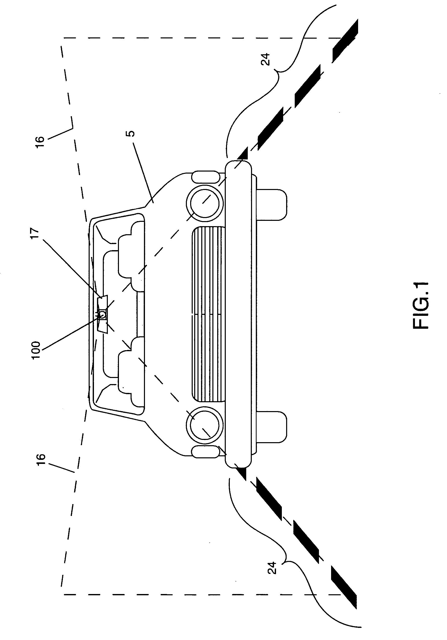
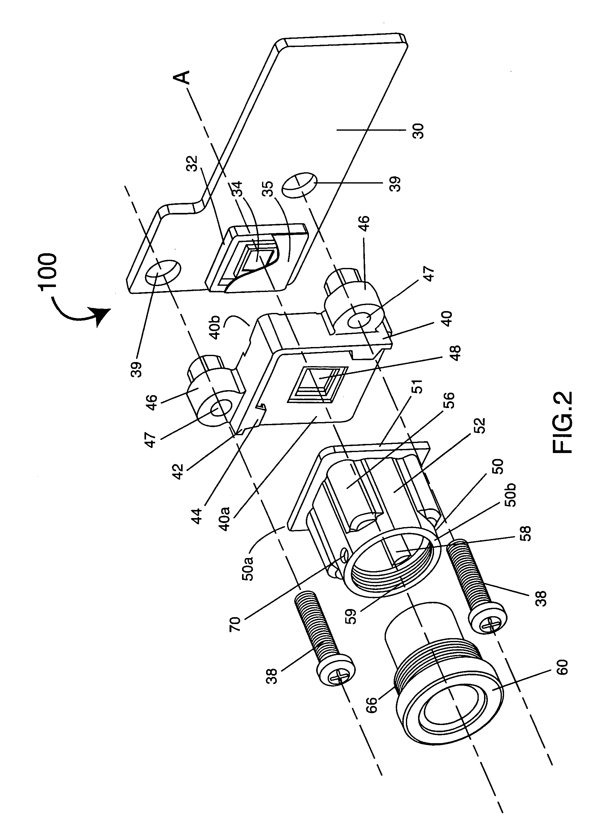
[0026]FIG. 1 illustrates a vehicle 5 employing an imaging system 100 with a lens mount system in accordance with a preferred embodiment of the present invention. The imaging system 100 may form part of a lane departure warning system in one preferred application. Imaging system 100 employs at least one camera on the stem of the rear-view mirror 17. Other locations and additional cameras may also be employed, however, as described in U.S. patent application Ser. No. 10 / 373,150 filed Feb. 24, 2003, the disclosure of which is incorporated herein by reference in its entirety. The imaging system 100 is oriented generally along the direction of vehicle travel. As a result, the imaging system 100 provides a field of view 16 oriented forward along the roadway to include a portion of the roadway including lane markers 24. The lens mount system of the present invention improves alignment accuracy to improve the accuracy of the imaging system 100 in imaging lane markers 24 in a lane departure ...


PUM


Abstract

A two piece lens mount system for mounting a lens in correct focus and alignment relative to a CMOS imaging device such that the optical axis of the lens is coincident with and perpendicular to the center of the active area of the imager array. The lens is secured by the axial pressure of flexible ribs that are symmetrically spaced around the internal bore of a lens holder and act on a smooth surface on the outside of the lens. This arrangement eliminates translation of the lens across the imager array. Another portion of the body of the lens is threaded such that the lens, when rotated about its optical axis may be focused or axially aligned. When a focus or axial alignment point is reached, a staking fluid may be added to the lens thread, through a hole in the lens holder to prevent de-focusing. The second component of the lens mount system, the lens mount base, is fixedly secured to an imager board on which is mounted a CMOS imager. The upper wall of the lens mount base is in close, parallel proximity to the optical flat of the imager and has a rectangular opening which restricts light from the lens to the active area of the imager, and more specifically prevents light from falling on the column amplifiers of the imaging device. The design of both components is such that they may be moved relative to each other with external fixturing, in front of a known target, until it is decided that the lens is directly over the center of the imager array. The lens holder and the lens mount base are then fixed together permanently using a laser weld process or any other plastic bonding technique.

Description

RELATED APPLICATION INFORMATION [0001] The present application claims the benefit of U.S. provisional patent application Ser. No. 60 / 609,977 filed on Sep. 15, 2004, the disclosure of which is incorporated herein by reference in its entirety.BACKGROUND OF THE INVENTION [0002] 1. Field of the Invention [0003] The present invention relates to vehicle mounted imaging systems for vehicle positioning and safety applications. More particularly, the present invention relates to imaging systems for vehicle mounted lane tracking systems. [0004] 2. Description of the Prior Art [0005] Image processing technologies are being designed and implemented for intelligent vehicles that are directed to improving vehicle safety. One significant example of such an image processing based safety system is a lane departure warning system. A typical lane departure warning (LDW) system includes a camera mounted in a vehicle, e.g. in the vehicle's rear-view mirror stalk at the center of the windshield, along wi...

Claims


Application Information

Patent Timeline
Patent Type & Authority Applications(United States)
IPC IPC(8): H01J5/02
CPCG02B27/62G02B13/001
Inventor JOHNSTON, DONAL
Owner ITERIS INC
Why Eureka
Try Eureka