Cylinder head gasket

a technology of cylinder head and sealing bead, which is applied in the direction of engine sealing, sealing arrangement, machine/engine, etc., can solve the problems of reducing the effect of the stopper lying radially inside the sealing bead and over the liner, and achieves the reduction or total elimination of the risk of impairing the spring-elastic behavior of the sealing bead, the effect of increasing the deformation strength of the stopper and less expensiv

Inactive Publication Date: 2006-03-16
ELRINGKLINGER AG
View PDF24 Cites 9 Cited by
  • Summary
  • Abstract
  • Description
  • Claims
  • Application Information

AI Technical Summary

Benefits of technology

[0008] The basic concept underlying the present invention is thus to combine two stoppers of fundamentally different design with each other, namely one stopper having a bead with an at least partially meander-shaped form, with a stopper made of, in particular, stamped (in a type of deep-drawing or flow-pressing process) discrete, i. e., individual, elevations. Such a combination results in quite a number of advantages:
[0009] With a meandering bead closed in the shape of a ring within itself as stopper there can be created around the combustion chamber through-opening, in addition to the sealing zone formed by the sealing bead to be protected, a second sealing zone (at least when the stopper is bearing, i. e. is pressed). On the other hand, a stopper formed by discrete elevations can be subjected to higher load without the stopper height being reduced, as the number of meander loops per length unit in a meandering bead—measured in circumferential direction of the combustion chamber through-opening—is limited for deformation reasons (space is required for the arc-shaped “reversal areas” of a meandering bead), whereas the “packing density” of stamped, discrete, i. e., individual, elevations can be increased almost optionally, which involves an increase in the deformation strength of the stopper. A so-called double stopper is generally used in cylinder head gaskets intended for engines with cylinder liners. In such engines, a certain lowering of a cylinder liner inserted into an engine block is to be anticipated during engine operation, which reduces the effect of the stopper lying radially inside the sealing bead and over the liner. For this reason, a further stopper lying radially outside the sealing bead and radially outside the liner over the actual engine block is used to reliably protect the sealing bead in the long term against excessive deformation. Since the cylinder liner, the engine block and the cylinder head (between which the cylinder head gasket is clamped) usually consist of different materials, with stoppers of different design one can take the different material characteristics into consideration. Finally, a tool for stamping discrete elevations is simpler and less expensive than a tool for stamping a meandering bead.
[0010] In an inventive cylinder head gasket, the meandering bead is preferably arranged radially inside the actual sealing bead to be protected by the stopper, i. e. between the sealing bead and the combustion chamber through-opening for sealing-off against combustion gases in front of the sealing bead by means of the above-mentioned second sealing zone and for shielding the actual sealing bead to be protected by the stopper from the hot combustion gases, whereby the risk of impairing the spring-elastic behavior of the sealing bead is reduced or totally eliminated. The other deformation delimiting device of different design then lies—seen from the combustion chamber through-opening—behind the sealing bead to be protected by the double stopper.

Problems solved by technology

In such engines, a certain lowering of a cylinder liner inserted into an engine block is to be anticipated during engine operation, which reduces the effect of the stopper lying radially inside the sealing bead and over the liner.

Method used


Image

  • Cylinder head gasket
  • Cylinder head gasket
  • Cylinder head gasket

Examples


Embodiment Construction

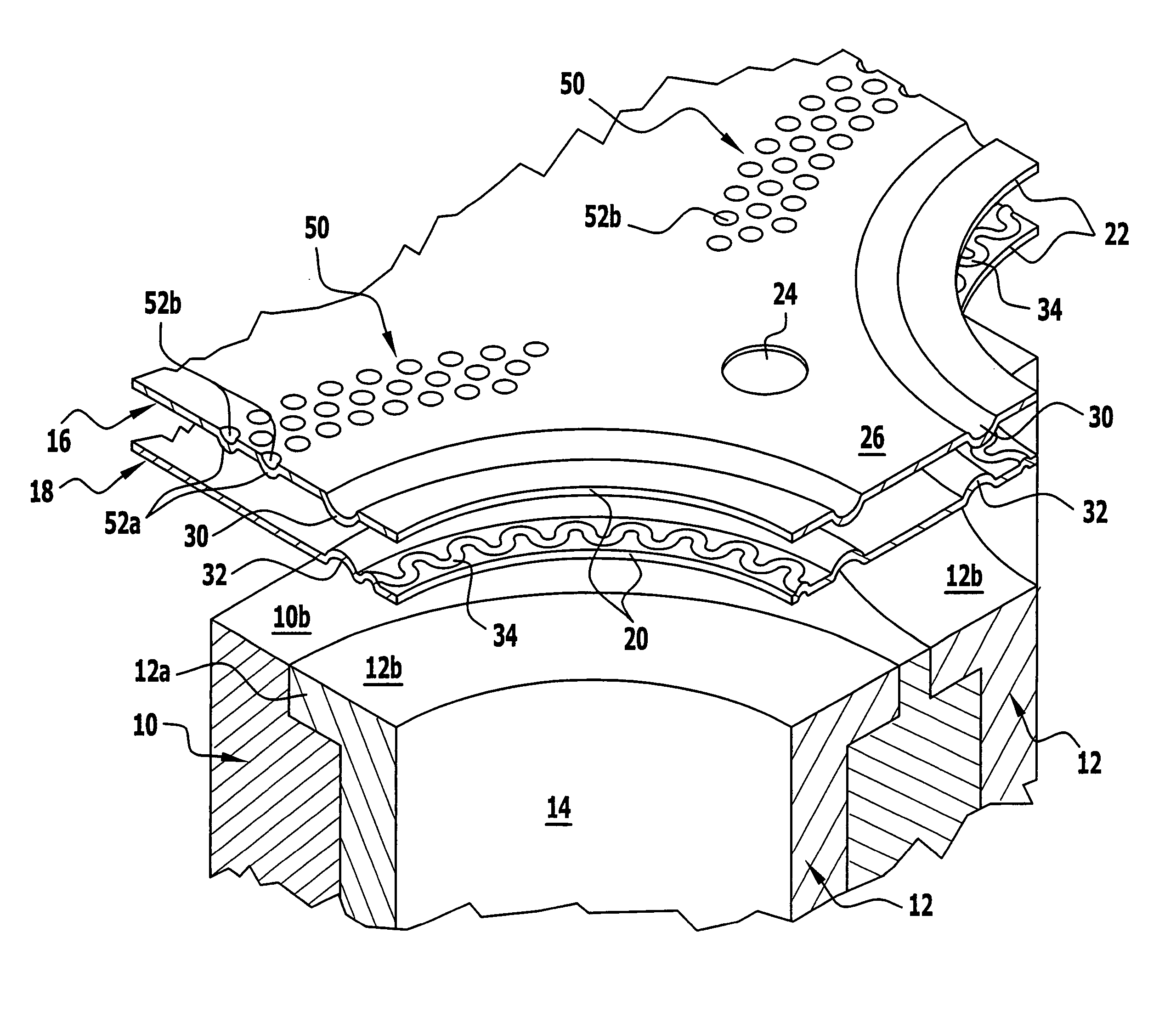
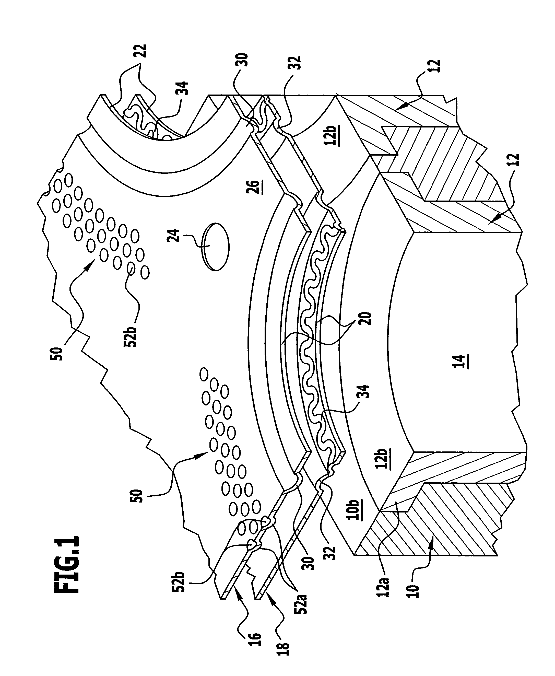
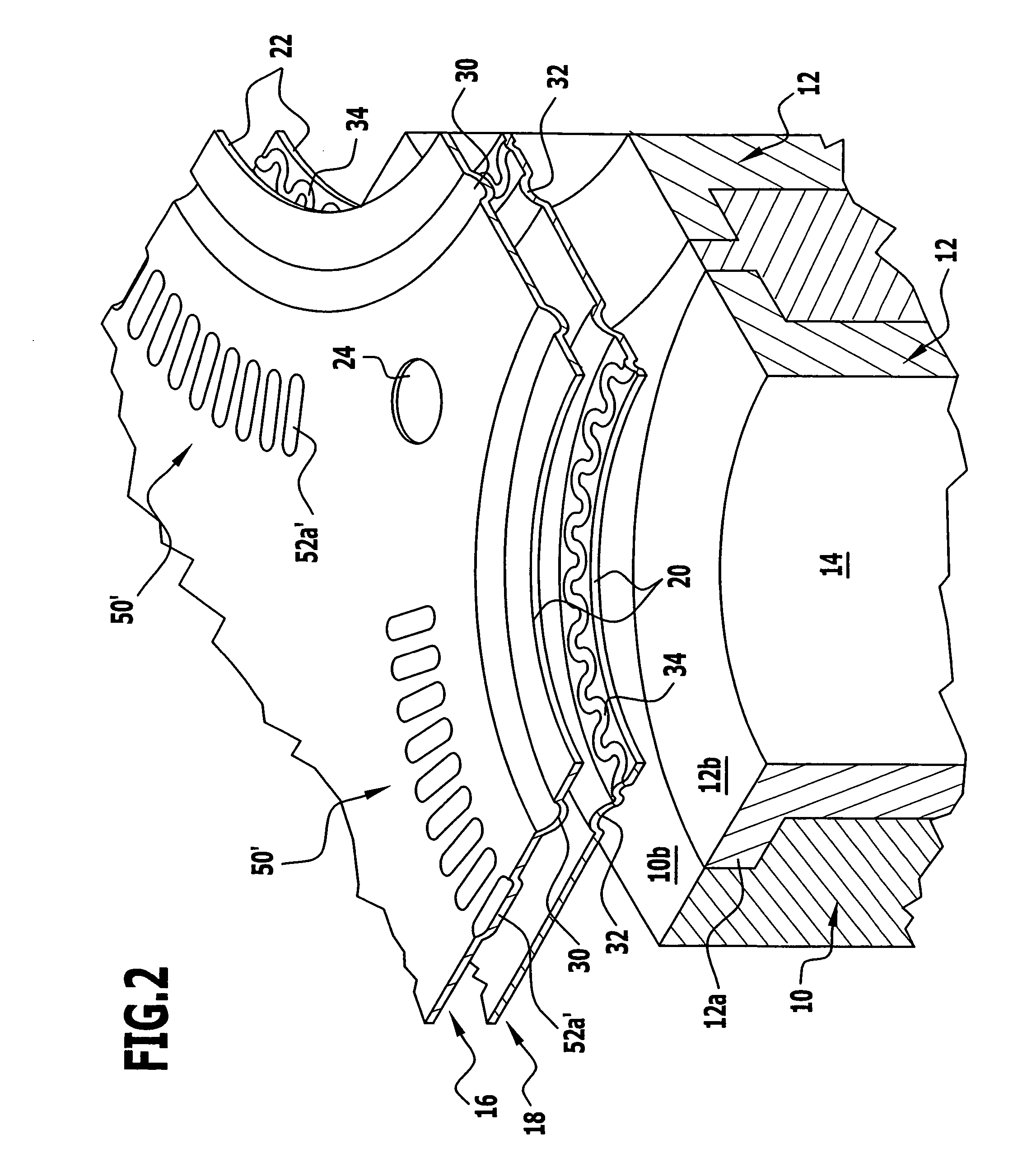
[0018]FIG. 1 shows part of a crankcase or engine block 10 in which there is inserted a cylinder liner 12 whose bore forms part of a combustion chamber 14 of the engine. The liner 12 has at the top a liner collar 12a, whose upper end face forms a sealing surface 12b, which is intended to be flush with, i. e., at the same level as, a sealing surface 10b formed by an upper end face of the engine block 10.

[0019] There is clamped between the sealing surfaces 10b, 12b and a sealing surface, facing these, of a cylinder head, not illustrated, a cylinder head gasket which in the illustrated embodiment has a gasket plate comprised of an upper functional layer 16 and a lower functional layer 18 made of sheet spring steel. These could be the only metal layers of the gasket plate of the inventive cylinder head gasket, but the latter could also comprise further metal layers, for example, a smooth, i. e., flat layer lying between the two functional layers 16, 18 and / or an upper and / or a lower cov...


PUM


Abstract

Cylinder head gasket having a single-layered or multilayered metallic gasket plate with sealing beads in at least one metal layer, which are elastically deformable in height and surround the combustion chamber through-openings, and deformation delimiting devices which delimit the flattening of the sealing beads; in order to achieve as good a sealing function as possible in the long term and as good a protection as possible of the sealing beads against inadmissibly high deformations during operation of the engine, deformation delimiting devices, one of which is formed by a meandering bead stamped into a metal layer, and the other by a plurality of elevations stamped out of a metal layer, are provided radially inside and radially outside the sealing beads.

Description

[0001] The present disclosure relates to the subject matter disclosed in German application No. 10 2004 044 851.5 of Sep. 10, 2004, which is incorporated herein by reference in its entirety and for all purposes. BACKGROUND OF THE INVENTION [0002] The invention relates to a cylinder head gasket with a single-layered or multilayered, at least substantially metallic gasket plate comprising for a sealing bead which is elastically deformable in height and surrounds a combustion chamber through-opening of the gasket a so-called double stopper for delimiting the bead deformation with a deformation delimiting device arranged radially inside the sealing bead and radially outside the sealing bead. [0003] Such a cylinder head gasket is disclosed in EP-1 298 364-A of ElringKlinger AG (see lines 1-3 of page 6). In a gasket with a multilayered gasket plate, the deformation delimiting devices (stoppers) can all be provided on the sheet metal layer (so-called functional layer) provided with the sea...

Claims


Application Information

Patent Timeline
Patent Type & Authority Applications(United States)
IPC IPC(8): F02F11/00F16J15/08
CPCF16J15/0818F16J2015/0868F16J2015/085F16J15/0825
Inventor TIEFENBACH, THOMASDIEZ, ARMINFRITZ, WOLFGANG
Owner ELRINGKLINGER AG
Why Eureka
Try Eureka