Quick-clamping device with hub centering ring for securing a vehicle wheel on the shaft of wheel-balancing machines

a technology of balancing machine shaft and hub centering ring, which is applied in the direction of turning apparatus, metal-working holders, supporters, etc., can solve the problems of tedious and particularly demanding devices, inability to dynamically balancing the vehicle wheel, and inability to use the device of the prior art. , to achieve the effect of simplifying the connection of the rim to the flang

Inactive Publication Date: 2006-03-16
WARKOTSCH HORST
View PDF32 Cites 17 Cited by
  • Summary
  • Abstract
  • Description
  • Claims
  • Application Information

AI Technical Summary

Benefits of technology

[0008] An object of the present invention is to create a quick clamping device for securing vehicle wheels to a wheel balancing machine, and in which the disadvantages of the prior art quick clamping devices are avoided and, in particular, the securing of the rim to the flange is simplified.

Problems solved by technology

This is laborious and particularly demanding, if the clamping element is a clamping nut, which is screwed by hand onto the outer threads of the shaft.
This device of the prior art is tedious to use, since the truncated-cone-shaped and cup-shaped parts must first be separated and then, after the object to be centered has been mounted, must then be brought back together, before clamping can be performed.
A further disadvantage can be found in the fact that when clamping a vehicle wheel the contact edge of the cup-shaped part makes contact with the side of the vehicle rim facing away from the truncated-cone-shaped part, with which the rim does not make contact on the securing flange of the axle when it is mounted on the vehicle.
A dynamic balancing of the vehicle wheel is therefore not possible.
The decisive disadvantage, however, can be found in the fact that following clamping the axial position of the device is not set, therefore making this prior art device unsuitable for clamping a vehicle wheel onto the shaft of a balancing machine.
This prior art device therefore has the same disadvantages as those of the device proposed in DE 38 06 755 C2 mentioned above.

Method used


Image

  • Quick-clamping device with hub centering ring for securing a vehicle wheel on the shaft of wheel-balancing machines
  • Quick-clamping device with hub centering ring for securing a vehicle wheel on the shaft of wheel-balancing machines
  • Quick-clamping device with hub centering ring for securing a vehicle wheel on the shaft of wheel-balancing machines

Examples


Embodiment Construction

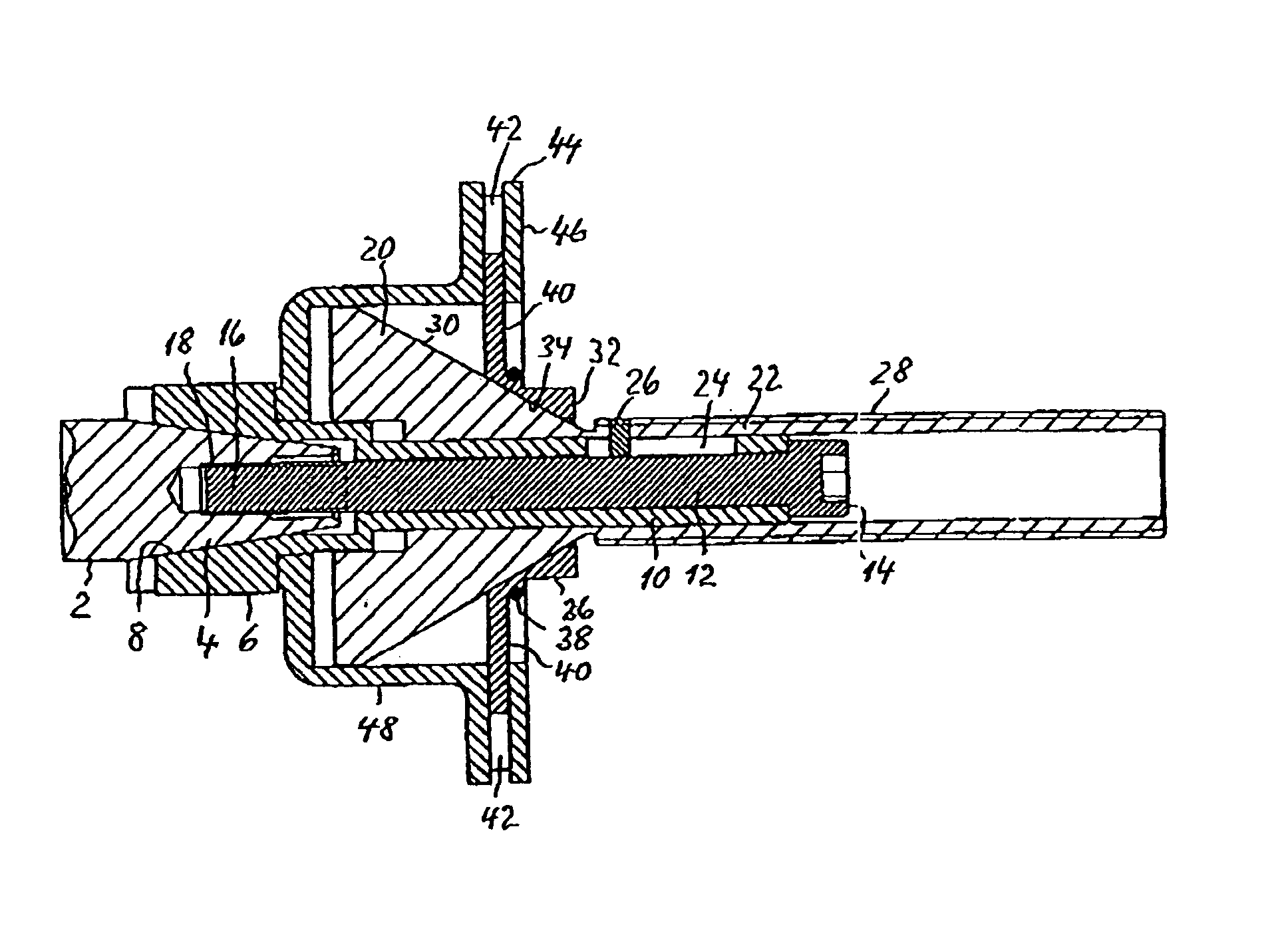
[0025]FIG. 1 shows the end of the shaft 2 of an unillustrated wheel balancing machine. Disposed on a conical section 4 of the shaft 2 is an extending part 6 with a complementary conical inner bore 8. The extension of the extending part 6 essentially comprises an axially extending tubular part 10, in which a screw 12 extends, and which is provided with its head 14 at the end of the tubular part 10 and is screwed into a threaded hole in the conical part 4 with its threads facing away from the head 14 so that the extending part 6 is securely mounted on the conical part 4.

[0026] A cone 20 is mounted axially displaceable on the tubular part 10 with narrow clearance. Extending from its point is a tubular element 22, which is formed from the same piece as the cone 20 and, like the cone, is axially displaceable on the tubular part. Extending over a defined length in the tubular part 10 is a groove 24, in which the rod 26 provided in the tubular element 22 is displaceably engaged, thereby p...


PUM


Abstract

Quick-clamping device with a hub centering ring secures a vehicle wheel rim on the shaft of a wheel-balancing machine. Securely attached to the shaft is a flange to facilitate a friction fit placement on the rim. For centering, a conical assembly is provided, including an inner bore to be slid onto the shaft of the balancing machine, as well as an outer centering surface for engaging the centering hole of the rim. Conical assembly includes a cone, from the apex of which a tubular element extends, and which is mounted with its inner wall axially displaceable on the shaft or an extension of it, and a clamping element for tightening the rim against the flange abuts its outer wall. Advantageously, until reaching the centering and clamping position by using the clamping element, quick-clamping device ensures no forces must be overcome. This provides ease of use of the quick-clamping device.

Description

CROSS REFERENCE TO RELATED APPLICATIONS [0001] This application claims the priority of German Application No. 10 2004 044 287.8, filed Sep. 10, 2004, which is incorporated herein by reference. FIELD OF THE INVENTION [0002] The invention relates to a clamping device for fixing a wheel rim of a vehicle wheel to a shaft of a balancing machine. More particularly, the invention relates to a quick-clamping device for securing a vehicle wheel to a shaft of a balancing machine. Even more particularly, the invention relates to a quick-clamping device for adjustably, fixedly securing a vehicle wheel rim to a centering shaft of a wheel balancing machine with little effort. BACKGROUND OF THE INVENTION [0003] DE 38 08 755 C2 describes a quick-clamping device in which the conical assembly is pressed into the centering hole of the vehicle wheel rim by a spring exerting force axially. The spring travel is determined so that for rim centering holes of different diameters the conical assembly engages...

Claims


Application Information

Patent Timeline
Patent Type & Authority Applications(United States)
IPC IPC(8): B23B31/40G01M1/04
CPCY10T279/1045G01M1/045
Inventor OHNESORGE, AXEL
Owner WARKOTSCH HORST
Why Eureka
Try Eureka