Regenerative braking system for motor vehicles

a regenerative braking and motor vehicle technology, applied in the direction of braking systems, brake components, gearing, etc., can solve the problems of incompatibility between the improvement of fuel efficiency and the improvement of stability and degradation of fuel efficiency, and degradation of the stability and/or controllability of the vehicle, so as to achieve the effect of more reduction of the amount of regenerative braking

Inactive Publication Date: 2006-03-16
NISSAN MOTOR CO LTD
View PDF4 Cites 64 Cited by
  • Summary
  • Abstract
  • Description
  • Claims
  • Application Information

AI Technical Summary

Benefits of technology

[0015] According to a first aspect of the present invention there is provided a regenerative braking system for motor vehicles comprising: a generator that is connected with at least one wheel set, the generator being capable of applying regenerative brake torque to the one wheel set by generating electricity; a regenerative braking control means that controls a regenerative braking amount of the generator based on at least demand brake force amount; an actual wheel speed variation calculating means that calculates an actual wheel speed variation between actual outer wheel speed of an outer wheel of steerable wheels and actual inner wheel speed of at least one wheel of a front wheel set and a rear wheel set; a cor

Problems solved by technology

The above known conventional regenerative braking systems, however, encounter a problem that improvement in fuel efficiency and improvement in stability and controllability of a vehicle are incompatible with each other.
The first conventional system loses a margin for recoverable regenerative energy, resulting in degradation in fuel efficiency, because it prohibits application of the regenerative brake torque in a not-understeer range, for example a neutral range where the vehicle runs with a large steering angle and with road grip.
The second conventional system might cause excessive oversteer on the medium or high friction road, resulting in degradation in stability and/or controllability of the vehicle, because it does not reduce the regenerative brake torque even when excessive oversteer causes during the vehicle runs on a medium or high friction road.
The

Method used


Image

  • Regenerative braking system for motor vehicles
  • Regenerative braking system for motor vehicles
  • Regenerative braking system for motor vehicles

Examples


first embodiment

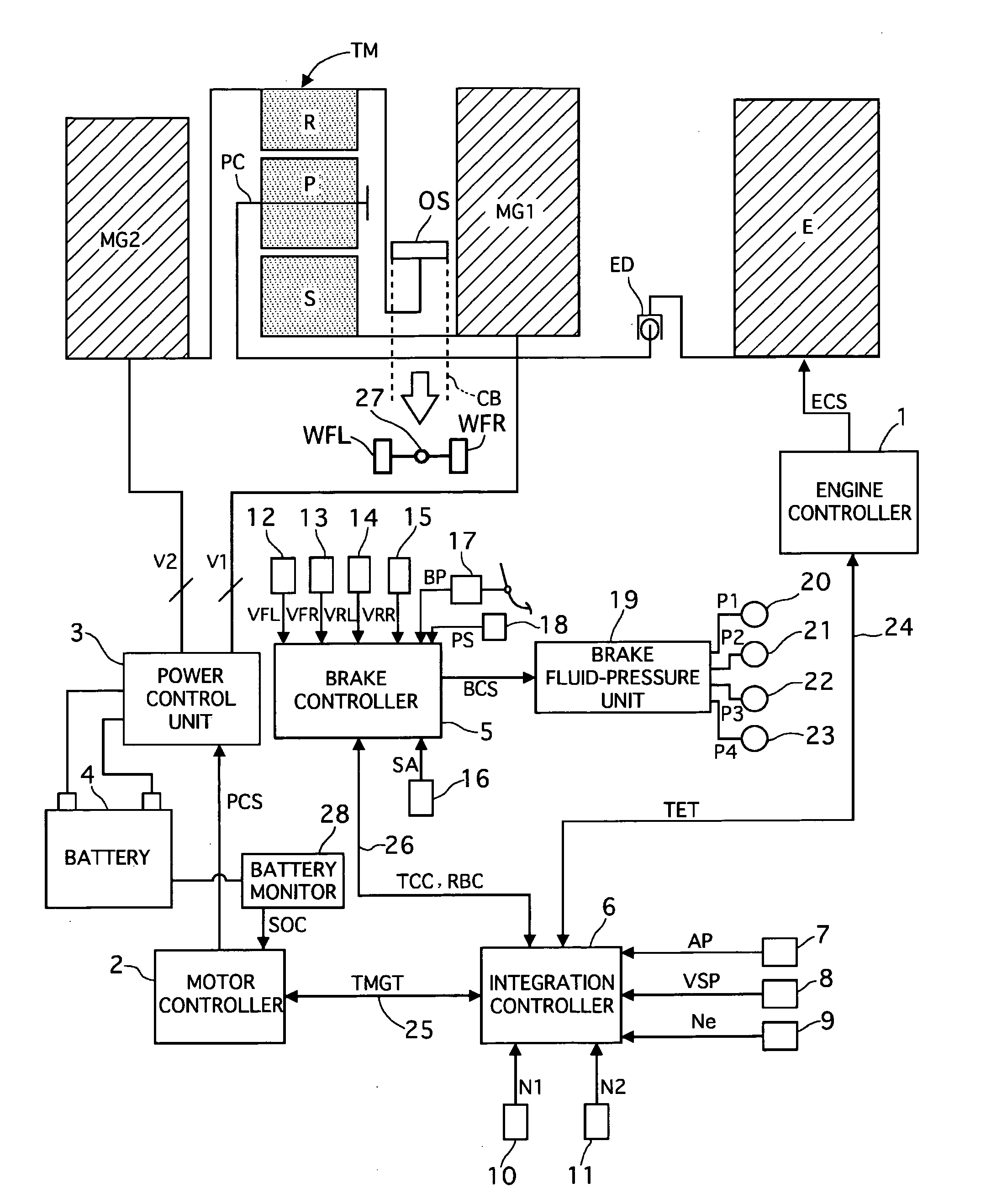
[0043]FIG. 1 shows a schematic diagram showing a power train and a braking system of a hybrid electric vehicle. The vehicle is equipped with an engine E, a first motor / generator MG1, a second motor / generator MG2, a power split device TM, and a braking system including the regenerative braking system of the present invention and a fluid-pressure brake system. This vehicle is a front-wheel drive vehicle, which is propelled by using a combination of the engine E and the motor / generators MG1 and MG2.

[0044] The engine E employs a gasoline engine, a diesel engine, and the like, and is operated based on an engine control signal outputted from an engine controller 1.

[0045] The first and second motor / generators MG1 and MG2 are synchronous motor / generators with a rotor embodying plural interior permanent magnets inside of it and a stator containing the rotor and wound around by windings. The first and second motor / generators MG1 and MG2 are independently controlled based on a power control s...

second embodiment

[0127] Next, a regenerative braking system of a second embodiment according to the present invention will be described with reference to the accompanying drawing of FIG. 22.

[0128] This regenerative braking system is equipped with a demand regenerative torque calculating module, a regenerative torque demand limit calculating part, and a demand regenerative torque selecting module.

[0129] The demand regenerative torque limit calculating part, as shown in FIG. 22, includes a front wheel speed variation calculating module 311, a vehicle body speed calculating module 312, an estimated front wheel speed variation calculating module 313, an estimated understeer amount calculating module 314, and a regenerative amount maximum limit calculating module 315′.

[0130] The front wheel speed variation calculating module 311 is electrically connected to a front left wheel speed sensor and a front right wheel speed sensor, the vehicle body speed calculating module 312 is electrically connected to a ...

third embodiment

[0137] Next, a regenerative braking system of a third embodiment according to the present invention will be described with reference to the accompanying drawings of FIGS. 23 and 24.

[0138] The regenerative braking system of the third embodiment is equipped with a demand regenerative torque calculating module, a demand regenerative torque maximum limit calculating part 31, and a demand regenerative torque selecting module.

[0139] The demand regenerative torque maximum limit calculating part 31 is, as shown in FIG. 23, provided with a front wheel speed variation calculating module 311′, a vehicle body speed calculating module 312, an estimated front wheel speed variation calculating module 313, an estimated understeer amount calculating module 314′, and a regenerative amount maximum limit calculating module 315″.

[0140] The front wheel speed variation calculating module 311′ is used for obtaining an actual front wheel speed variation VWFDIF as actual steering amount information. The ca...


PUM


Abstract

A regenerative braking system has a generator connected to at least one wheel set to apply regenerative brake torque to it by generating electricity, a regenerative braking control means controlling a regenerative braking amount, an actual wheel speed variation calculating means calculating an actual wheel speed variation between actual outer-wheel speed of an outer wheel of steerable wheels and actual inner-wheel speed of at least one wheel of front and rear wheel sets, a correspondent wheel speed variation calculating means calculating a correspondent wheel speed variation corresponding to an outer-to-inner wheel speed variation of the steerable wheels with road grip, a steer characteristic judging means judging strength of a steer characteristic based on the correspondent wheel speed variation and the actual wheel speed variation, and a regenerative braking amount compensating means compensating the amount to be more decreased as the steer characteristic becomes stronger.

Description

BACKGROUND OF THE INVENTION [0001] 1. Field of the Invention [0002] The present invention relates to a regenerative braking system that is used for motor vehicles, such as hybrid electric vehicles or electric vehicles, and capable of applying regenerative brake torque to wheels by an electric generator connected with the wheels. [0003] 2. Description of the Related Art [0004] A regenerating braking system for motor vehicles controls regenerative brake torque acting on wheels based on a so as to improve fuel efficiency and ensure stability and controllability of a vehicle. Such a regenerative braking system is disclosed in Japanese patents laid-open publication Nos. 2000-050409, 2000-270409, and (Tokkaihei) 05-161209. [0005] Japanese patent laid-open publication No. 2000-050409 discloses a regenerative braking system (a first conventional system) having an electric generator connected with front wheels. This first system is capable of applying regenerative brake torque to the front w...

Claims


Application Information

Patent Timeline
IPC IPC(8): B60T8/64
CPCB60K1/02Y02T10/7275B60K6/40B60K6/445B60T1/10B60T2201/16B60T2270/604B60T2270/608B60W10/06B60W10/08B60W10/184B60W20/00B60W30/18127B60W2510/207B60W2520/28F16H2037/0866Y02T10/6286Y02T10/6239B60L7/18B60L7/26B60L15/2036B60K6/365Y02T10/72Y02T10/62Y02T10/64B60W2540/18B60W20/13B60W2520/18
Inventor TOYOTA, HIROMITSUKONISHI, MASARUSUGIMOTO, TOMONAGAISONO, YOICHI
Owner NISSAN MOTOR CO LTD
Why Eureka
Try Eureka