

Battery pack
a battery pack and battery technology, applied in the field of batteries, can solve problems such as overheating of batteries
- Summary
- Abstract
- Description
- Claims
- Application Information
AI Technical Summary
Benefits of technology
Problems solved by technology
Method used
Image

Examples
Embodiment Construction
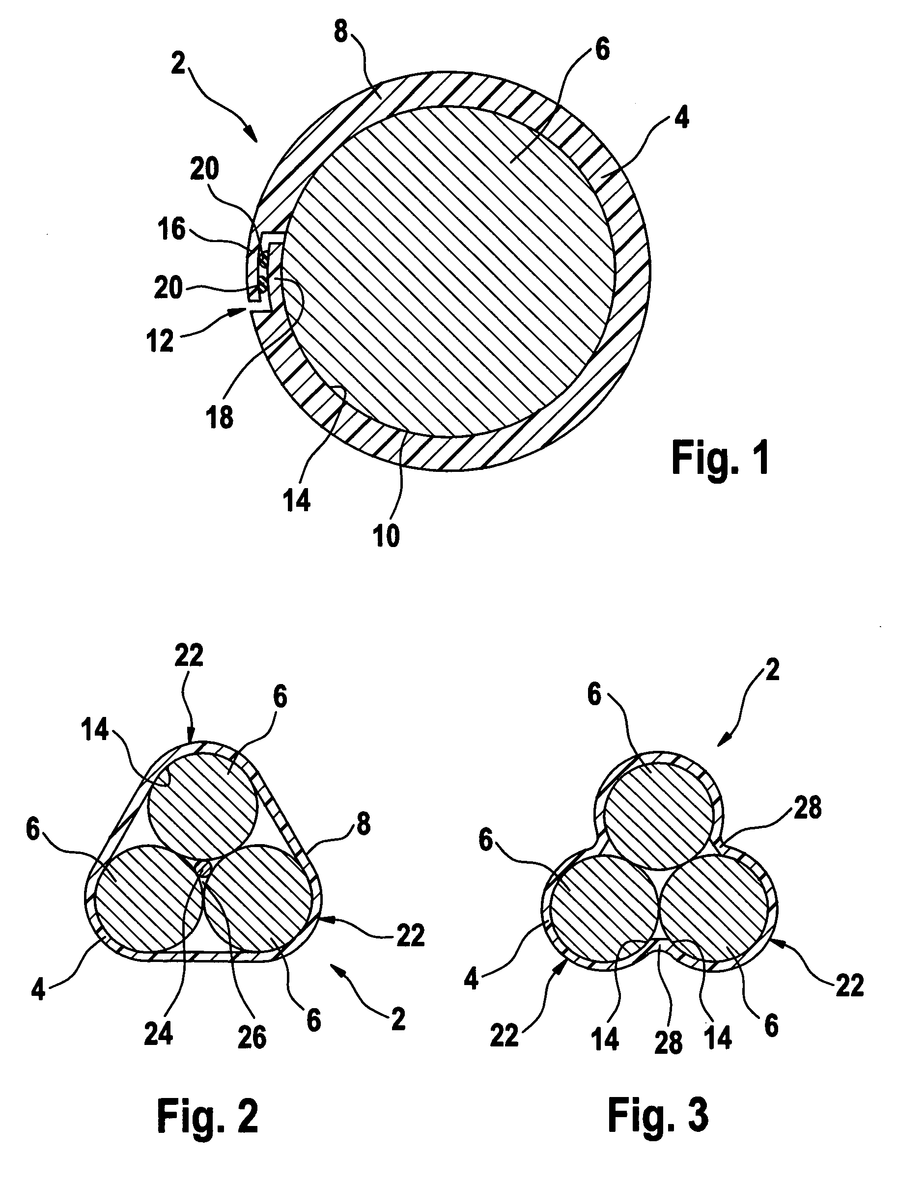
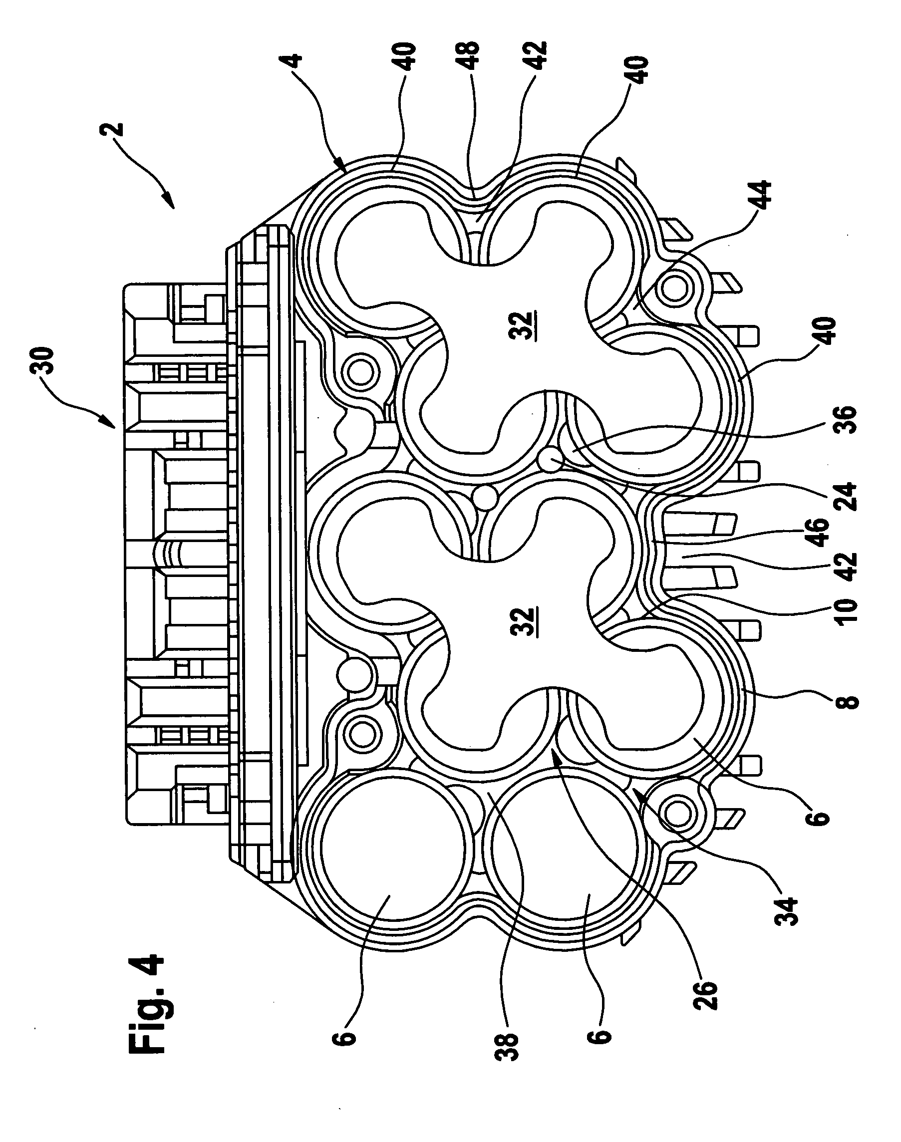
[0017] The battery packs 2 shown in the drawings are used as a power supply for an electrical device such as a hand-guided power tool (not shown). They are essentially comprised of a housing 4 made of injection-molded plastic, one or more tiers of cylindrical battery cells 6 contained inside the housing 4, and a cover (not shown) that closes the housing 4 at the end surface of the uppermost tier of cells 6. The cover, which as a rule is constituted by a part of the electrical device, has two contacts that come into contact with terminals of the battery pack when the housing 4 is closed in order to connect the series-connected or parallel-connected cells 6 contained in the housing 4 to a circuit of the consumer of the electrical device.
[0018] The housing 4 has essentially one end wall (not shown) facing one end surface of the cells and a circumference wall 8 that is integrally joined to the end wall and partitions off the cylindrical circumference walls 10 of the cells 6 from the su...
PUM
| Property | Measurement | Unit |
|---|---|---|
| power | aaaaa | aaaaa |
| circumference | aaaaa | aaaaa |
| elastic deformation | aaaaa | aaaaa |
Abstract
Description
Claims
Application Information