Input device for improving man-machine interface

a technology of input device and interface, which is applied in the direction of mechanical control device, manual control with single controlling member, instruments, etc., can solve the problems of lack of direct and natural response, low interface level between human operator and apparatus, and lack of pointing device, so as to achieve more direct and natural connection

Inactive Publication Date: 2006-03-16
AVIX
View PDF20 Cites 10 Cited by
  • Summary
  • Abstract
  • Description
  • Claims
  • Application Information

AI Technical Summary

Benefits of technology

[0007] One object of the present invention is to provide a means of forming an improved interface between the human operator and the machine through an input device capable of providing a more direct and natural feeling of connection between the control movements of the human operator and the corresponding screen display as output by a data processing device.

Problems solved by technology

As a result, a feeling of direct and natural response is lacking between the operation of the pointing device and corresponding output of the host device as viewed by the graphic conditions displayed on the screen.
This lack of natural response results in a non-direct feeling of control and low level of interface between the human operator and the apparatus.
As a result, persons unfamiliar or unskilled in the use of a data processing or other computer-controlled devices have trouble adapting to their operation, and often give up before the necessary skill is attained.
Furthermore, people who become skilled in the operation of the devices are forced to adapt to the shortcomings of conventional pointing devices, and in doing so expend time and effort in developing a skill which should be unnecessary.

Method used


Image

  • Input device for improving man-machine interface
  • Input device for improving man-machine interface
  • Input device for improving man-machine interface

Examples


first embodiment

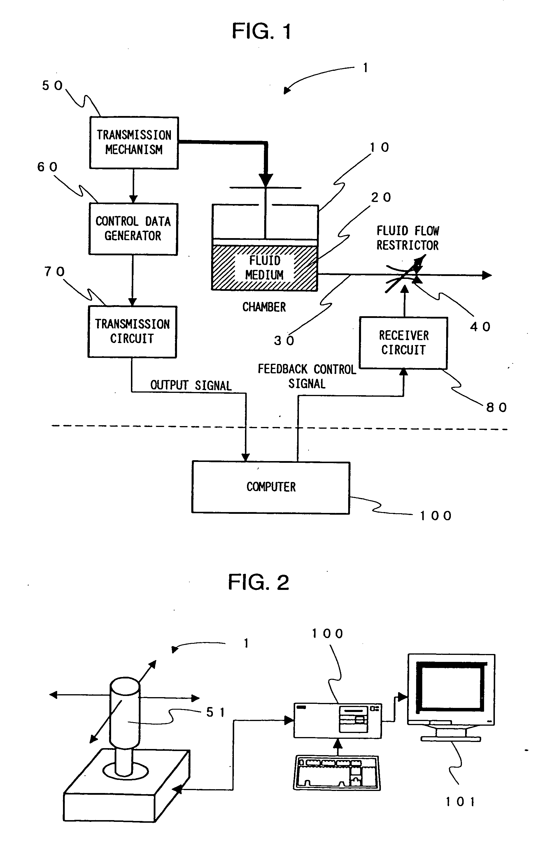
[0022]FIG. 2 shows a first embodiment of the input device invention in relation to the computer host device 100 to which it is connected therewith. An input device 1 is a pointing device structured as what is commonly referred to as a joy stick. A display 101 is connected to the computer host device 100 and displays cursor movement corresponding to the output of the input device 1. A lever 51, being manually operable, is installed to and protrudes from the upper part of the input device 1, and is supported at its base so as to be freely pivotable to any desired angle. Resultingly, the angular movement of the lever 51 corresponds to two dimensional display movements on the display 101. Moreover, the angle and speed of movement of the lever 51, in any direction starting from its perpendicular position, results in movement of the display cursor at a corresponding angle and speed.

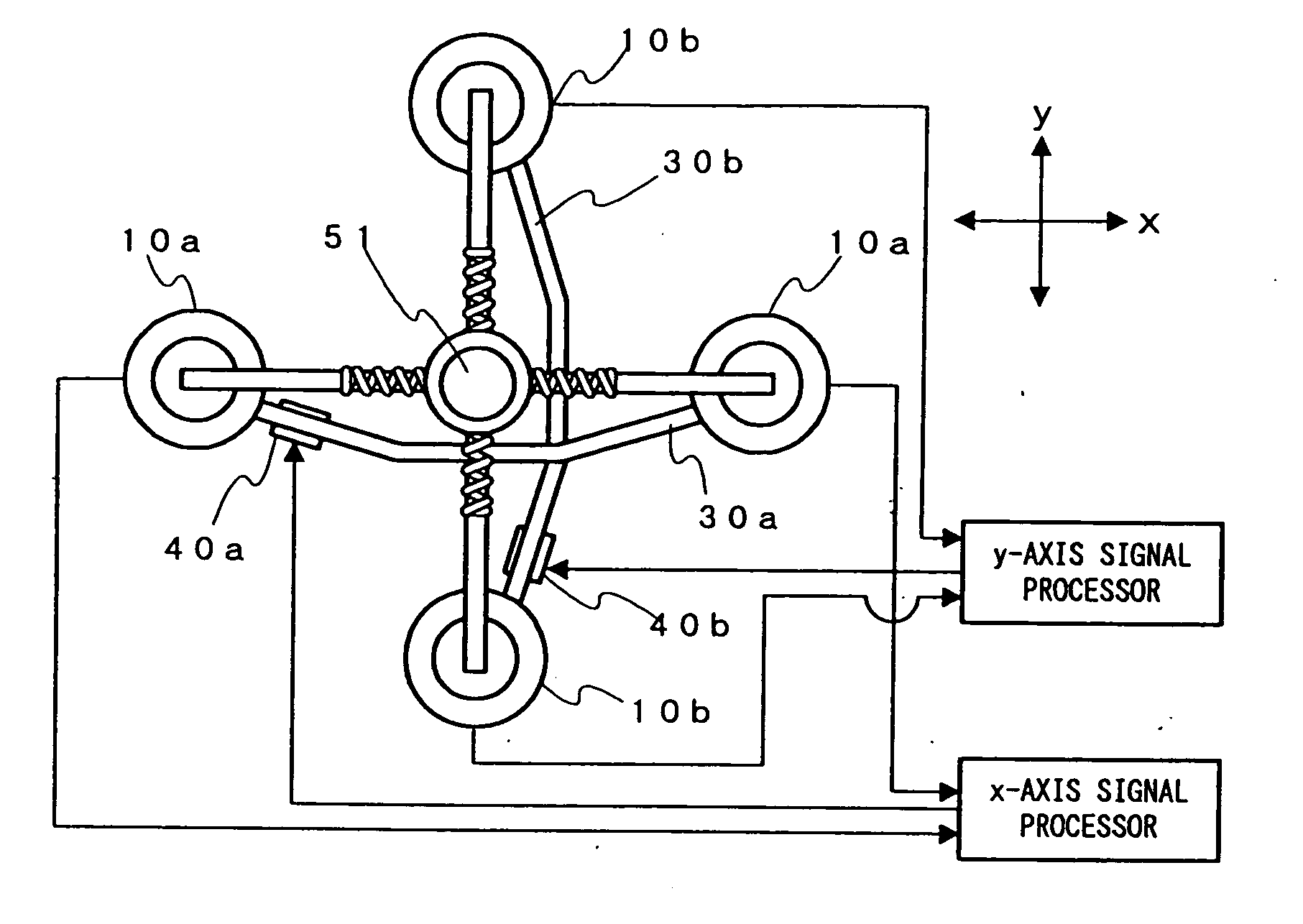
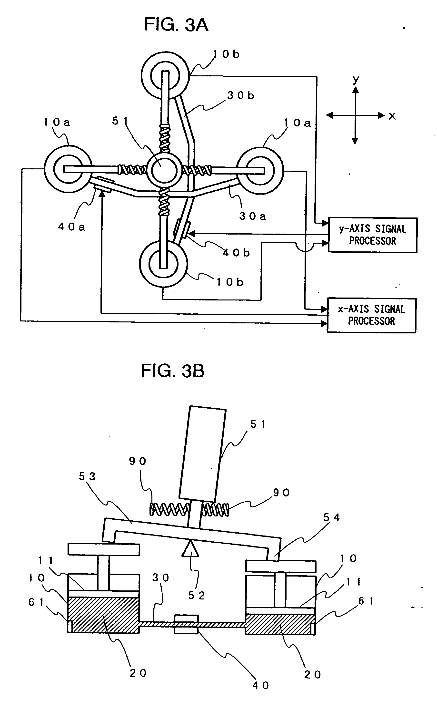
[0023] The structure of the input device 1 is shown in FIGS. 3A and 3B. FIG. 3A is a top view of the input ...

second embodiment

[0028]FIG. 4 shows a second embodiment of the invention in which a different structure of the aforesaid fluid flow variable restriction means is shown in a schematic form. Electrodes 41 are installed in mutually opposed orientation on the constriction pipe 30 so as to form a restricting orifice for the passage of sealed-in fluid medium 20, in this embodiment the fluid medium 20 being a fluid with electroviscous properties, hereafter termed EV fluid. A power supply 42 is installed as a means of providing drive power for the fluid flow variable restriction means. The response characteristics of the EV fluid 20 are shown in FIG. 5. The viscosity of the EV fluid existing between the mutually opposed electrodes 41 will increase as the applied voltage value emitted by the opposed electrodes becomes higher, thus making possible a function whereby the viscosity of the EV fluid can be changed through the application of a voltage-based control response signal to the mutually opposed electrode...

third embodiment

[0031]FIG. 8 shows an exterior view of a third embodiment of the man-machine interface invention in a configuration commonly known as a computer “mouse” pointing device. The mouse case is constructed with a flat bottom surface, control push-buttons 55a and 55b installed on its upper surface, and a connector cable installed to its front extremity. A roller ball is used in the lower case to track mouse movement directions. An elastic pad 56, which incorporates an elastic membrane as its upper surface, has been added to this conventional mouse structure. The pad 56 is structured so as to come into contact with the palm of the hand while the mouse is being operated, and is also structured so as to form the top of the aforesaid fluid chamber.

[0032]FIG. 9 is a schematic drawing showing a basic outline of the operation of the elastic pad 56. The pad 56 is structured so as to form the top part of the fluid chamber 10. When the elastic pad 56 is depressed as a result of pressure applied by ...


PUM


Abstract

An input device for improving man-machine interface is disclosed. The input device provides a more direct and natural relationship between the control movements of an operator and the output from the data processing system. One embodiment of the input device includes a fluid medium sealed inside a chamber, a control movement transmission mechanism connected to the chamber, a control data generating device monitoring and converting the operation of the inflow and outflow control mechanism into electrical signals, a transmission circuit for transmitting the signals to a computer, a fluid flow variable restriction device to variably control the volume of fluid flowing through the restrictor pipe, and a receiver circuit for driving the fluid flow variable restriction device based on control response signals output from the computer. The fluid medium flows into and out of the chamber through the restrictor pipe under control of the various mechanisms.

Description

CROSS REFERENCE TO RELATED APPLICATIONS [0001] This is a continuation of U.S. application Ser. No. 10 / 097,083, filed Mar. 13, 2002, which is a continuation of the U.S. application Ser. No. 09 / 035,617, filed Mar. 5, 1998, which claims the benefit of Japanese Patent Application 9-61176, filed Mar. 14, 1997, the entire contents of which applications are expressly incorporated herein by reference thereto. BACKGROUND OF THE INVENTION [0002] 1. Field of the Invention [0003] The present invention relates to a man-machine interface, also referred to as an input device, of the type generally used to manually input control signals to a computer or other data processing systems. [0004] 2. Description of the Related Art [0005] Manually controlled signal input devices used with data processing systems often take the form of pointing devices typically including a mouse or joystick. These pointing devices are controlled by a human operator in order to control movement of a cursor on a computer scr...

Claims


Application Information

Patent Timeline
Patent Type & Authority Applications(United States)
IPC IPC(8): G09G5/08G06F3/0338G05G9/047G06F3/038G06F3/033
CPCG05G9/047G05G2009/0474G05G2009/04766G06F3/0383G06F3/0338G06F3/03543G06F3/016
Inventor TOKIMOTO, TOYOTAROMASATOSHI, OISHI
Owner AVIX
Why Eureka
Try Eureka