Method and apparatus for visually indicating mask violation locations

Inactive Publication Date: 2006-03-16
TEKTRONIX INC
View PDF8 Cites 27 Cited by
  • Summary
  • Abstract
  • Description
  • Claims
  • Application Information

AI Technical Summary

Benefits of technology

[0006] A digital storage oscilloscope has a display screen to display a waveform, and a mask defining compliant and non-compliant regions. A method of operating the oscilloscope includes receiving a signal, processing the signal, an

Problems solved by technology

For instance, a “ringing” in a signal that leads the signal to momentarily overshoot the desired voltage after a transition may violate the mask by a very small amount that is difficult to see on the display screen.
While effective for large, conspicuous violations, this is ineffective for small or slight violations that are

Method used


Image

  • Method and apparatus for visually indicating mask violation locations
  • Method and apparatus for visually indicating mask violation locations
  • Method and apparatus for visually indicating mask violation locations

Examples


Embodiment Construction

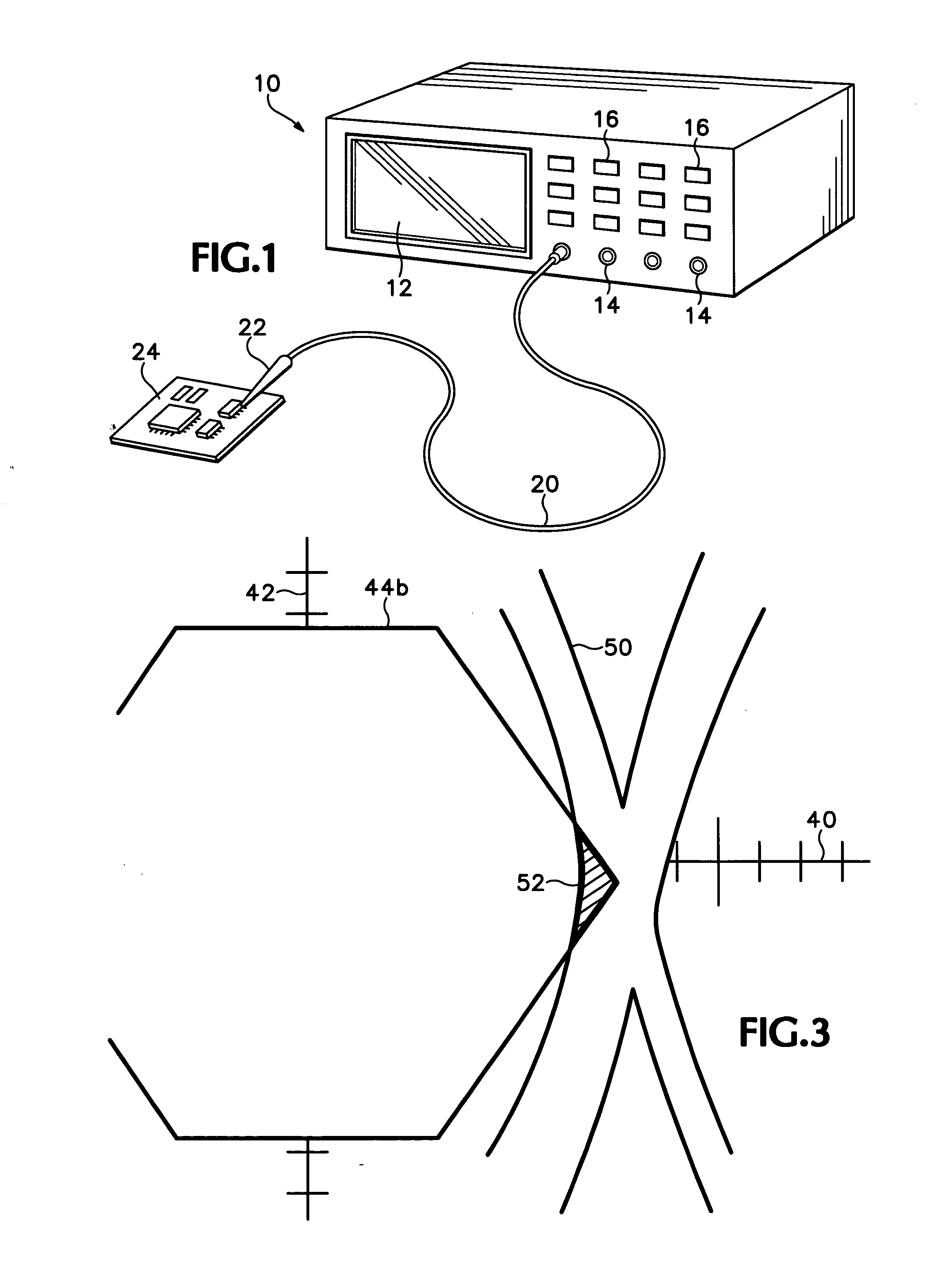
[0010]FIG. 1 shows a Digital Storage Oscilloscope (DSO) 10 according to the preferred embodiment of the invention. In most respects, it is functionally identical to the TDS3000-series oscilloscopes manufactured by Tektronix, Inc., of Beaverton, Oreg., and its successors and related models. The scope 10 has an electronic display screen 12, a plurality of input jacks 14, and an array of control buttons and knobs 16. A cable 20 is connected to an input, and has a probe 22 at a free end. The probe has a contact tip that operates to contact conductive nodes of a device 24 under test, which may be a prototype electronic assembly or circuit such as a circuit board. The scope 10 contains internal control circuitry connected to receive the input signal, and process it for display. The internal circuitry includes memory elements for storing data including standardized masks for different electronic performance and communication standards such as Ethernet protocol.

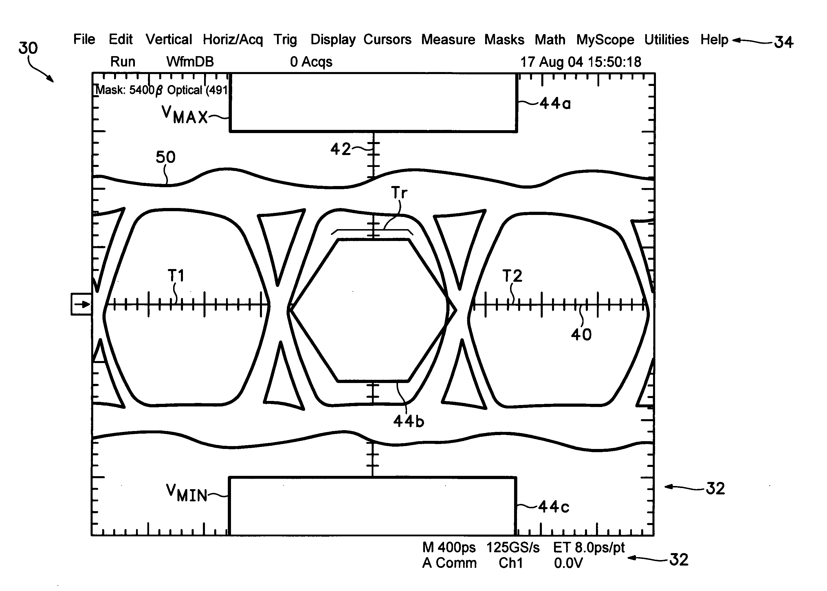
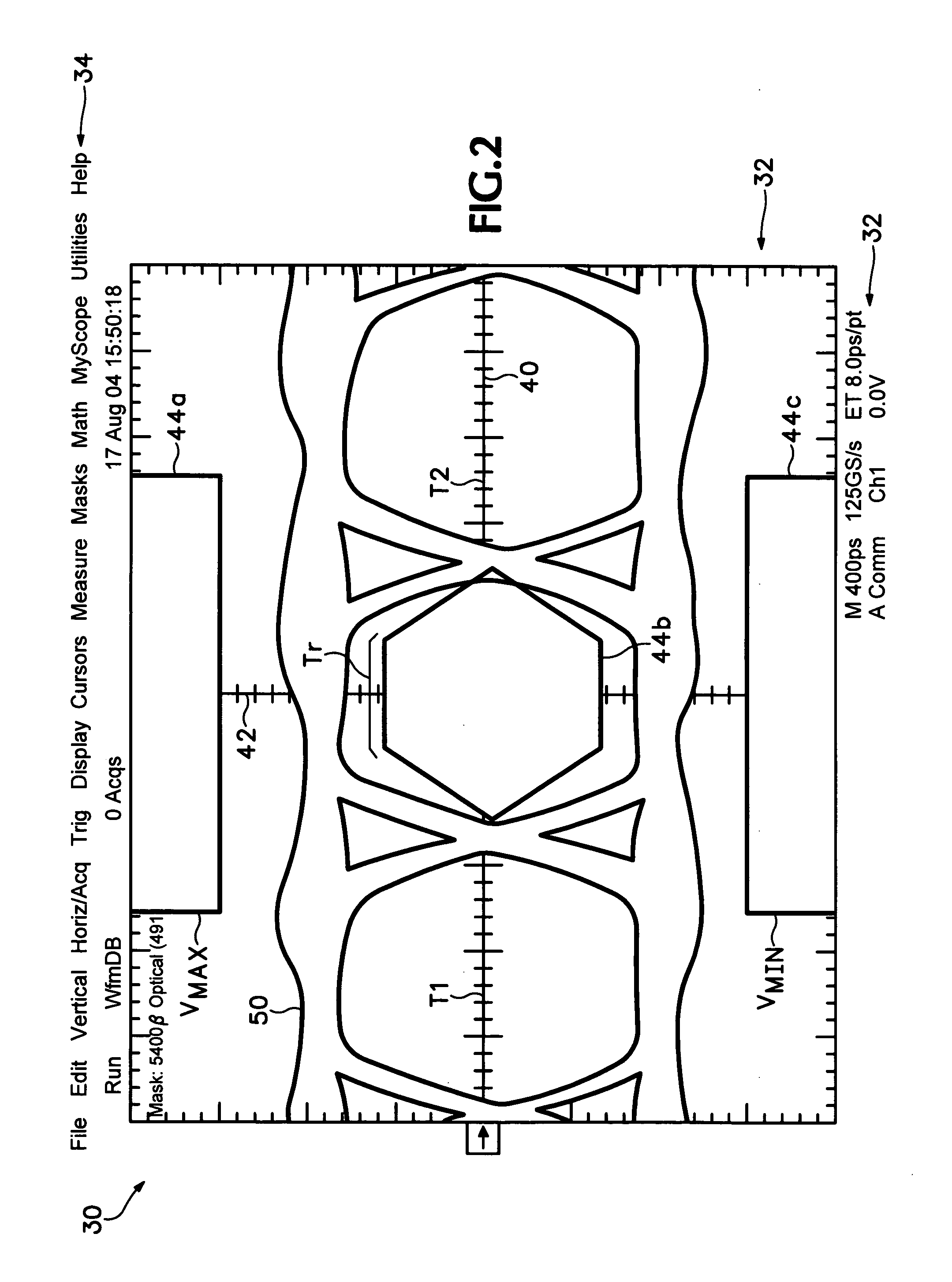
[0011]FIG. 2 shows a sample ...


PUM


Abstract

A digital storage oscilloscope having a display screen to display a waveform, and a mask defining compliant and non-compliant regions. A method of operating the oscilloscope includes receiving a signal, processing the signal, and displaying the signal on the screen. Portions of signals occupying the non-compliant region are displayed with a flashing illumination. The flashing illumination may be manually invoked to reveal small and inconspicuous violations.

Description

FIELD OF THE INVENTION [0001] The subject invention generally relates to the field of information display on an oscilloscope, and specifically refers to a more effective method and apparatus for visually indicating mask violations in a mask testing application. BACKGROUND OF THE INVENTION [0002] Digital storage oscilloscopes (DSO) are used to test electronic devices for operational performance. A device under test is operated, and probes connected to the DSO display the signal at selected outputs or nodes on the device. The signal is displayed on a display screen of the DSO for analysis. A typical DSO display has a time domain on the horizontal axis, and voltage domain on the vertical. For high-frequency digital logic signal analysis, the time axis is established to relate to a device clock signal, such that repetitious signal activity such as switching between high and low logic states are overlaid in alignment with prior signals, so that each possible logic state transition is ali...

Claims


Application Information

Patent Timeline
IPC IPC(8): G09G5/00
CPCG01R1/025G01R31/31708G01R13/029
Inventor ROBINSON, TRISTAN A.
Owner TEKTRONIX INC
Why Eureka
Try Eureka