Label printer with label supply feed control

Active Publication Date: 2006-03-16
PRIMERA TECH INC
View PDF22 Cites 18 Cited by
  • Summary
  • Abstract
  • Description
  • Claims
  • Application Information

AI Technical Summary

Benefits of technology

[0009] There is a space between the individual labels on the web and when feeding the labels past the tear bar, the space between labels overlies the tear edge. The printed label is not damaged f

Problems solved by technology

The printing operation is stopped when the web is clam

Method used


Image

  • Label printer with label supply feed control
  • Label printer with label supply feed control
  • Label printer with label supply feed control

Examples


Embodiment Construction

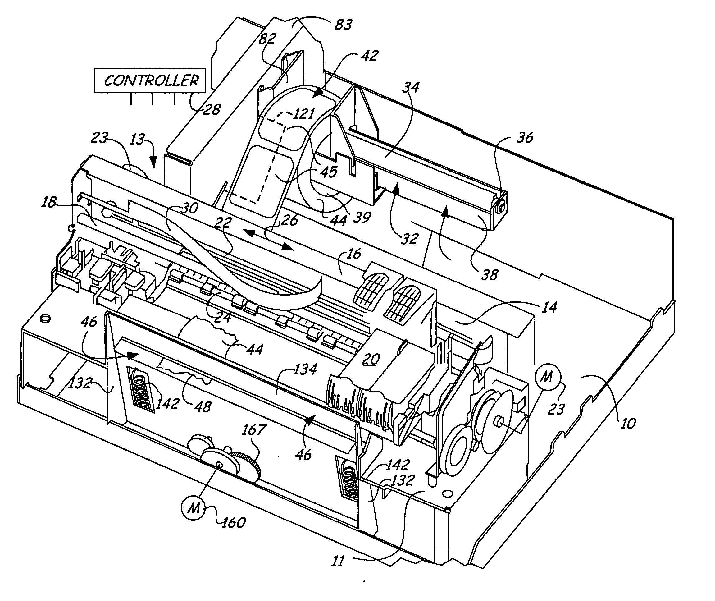
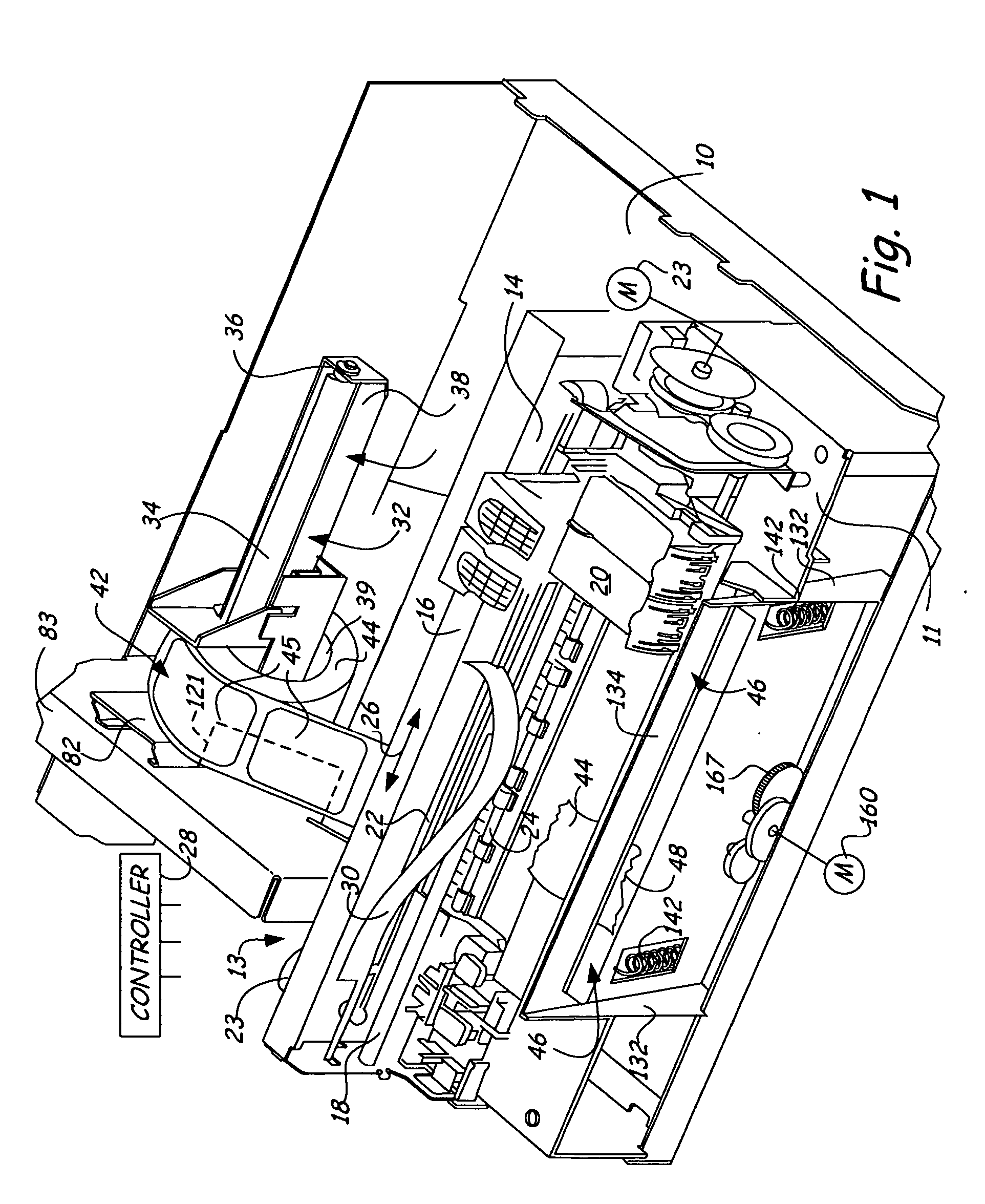
[0024] Referring to FIG. 1, a base plate forms a support for the various components including ap printer support plate 11. An ink jet printer 13 includes a frame assembly 14 of conventional design that is installed on the printer support plate 11. The ink jet printer frame assembly 14 has a main frame cross rib 16, supporting a guide rail 18 along which print heads 20 are driven in a normal manner, utilizing a controlled DC motor represented schematically at 23 and a drive belt 22. The guide rail 18 extends laterally of the path of labels to be printed.

[0025] The ink jet print heads 20 are controlled through a central controller 28 in a normal manner to provide print head movement and printing. The ink jet printer 13 includes feed rollers shown generally at 24 (FIG. 5), that are used for feeding material through an ink jet printer in a normal fashion. The ink jet printer heads 20 travel transversely along the guide rail 18, as indicated by the double arrow 26 (FIG. 1) under control...


PUM


Abstract

A label printer assembly has a support for a supply roll of labels on a flexible web which is fed into an ink jet printer for printing onto a label without contacting the label. After printing, the web carrying the printed label is fed beyond a tear strip to permit removing the printed label by tearing off the web at a space between the labels carried on the web. A feed roller is used to provide a slack loop on the output side of the supply roll that is controlled as to its size during printing, so the drag of the web on the printer feed rollers is reduced. The printer will selectively print bar codes onto the labels.

Description

[0001] This is a continuation-in-part of U.S. patent application Ser. No. 10 / 938,090, filed Sep. 10, 2004, entitled LABEL PRINTER, which is incorporated by reference, and priority on application Ser. No. 10 / 938,090 is hereby claimed.BACKGROUND OF THE INVENTION [0002] The present invention relates to a printer for printing information, such as bar codes, on adhesive backed labels. Blank labels are carried on a flexible web from a supply roll that is fed preferably through an ink jet printer. Printing labels using ink jet printing is fast, reliable, and involves a simple mechanism for advancing the roll of blank labels and controlling the feed rate of the roll. [0003] Being able to print a bar code on a label that can then be placed onto a box, product, or any container is useful, and printing the labels quickly, clearly and reliably is important. [0004] Generally speaking, thermal printers or similar printers have been used for bar code printing. The present device provides an ink je...

Claims


Application Information

Patent Timeline
IPC IPC(8): B41J2/01
CPCB41J3/01B41J15/005B41J3/4075
Inventor CUMMINS, ROBERT P.BRITZ, TODD A.TOLRUD, MICHAEL R.
Owner PRIMERA TECH INC
Why Eureka
Try Eureka