Mobile unit motion calculating method, apparatus and navigation system

a technology of motion calculation and mobile body, applied in the field of mobile body motion calculation technique, can solve the problems of large error in camera motion, difficult to eliminate an error, above-described conventional, etc., and achieve the effect of high accuracy

Active Publication Date: 2006-03-16
PANASONIC INTELLECTUAL PROPERTY CORP OF AMERICA
View PDF5 Cites 28 Cited by
  • Summary
  • Abstract
  • Description
  • Claims
  • Application Information

AI Technical Summary

Benefits of technology

[0036] According to the present invention, a two-stage motion calculation step is provided, in which a first motion is calculated on an assumed plane and a second motion is calculated using the first motion. Therefore, for example, even when a mobile body and a road surface are inclined, a motion of the mobile body can be calculated with high accuracy.

Problems solved by technology

However, the above-described conventional techniques have the following respective problems.
However, it is difficult to eliminate an error which occurs in the process of extracting the corresponding points.
When a camera motion is calculated from the erroneously extracted corresponding points, a large error occurs in the camera motion (another problem).
However, when this method is applied to images captured by a camera mounted on a mobile body, it is difficult to extract corresponding static points present on the same plane without an error.
Therefore, an error in a camera motion is increased due to an error in the process of extracting corresponding points (another problem).
However, the filtering process works only when a camera motion and a cause of an error follow a previously assumed model.
For example, when a vehicle runs at low speed, an influence of external disturbance, such as unevenness, a bump or the like on road surface, which is difficult to predict, is increased.
In this case, it is difficult to design a filter itself.
Therefore, when a parameter of a filter is not appropriate, an error is conversely increased.

Method used


Image

  • Mobile unit motion calculating method, apparatus and navigation system
  • Mobile unit motion calculating method, apparatus and navigation system
  • Mobile unit motion calculating method, apparatus and navigation system

Examples


first embodiment

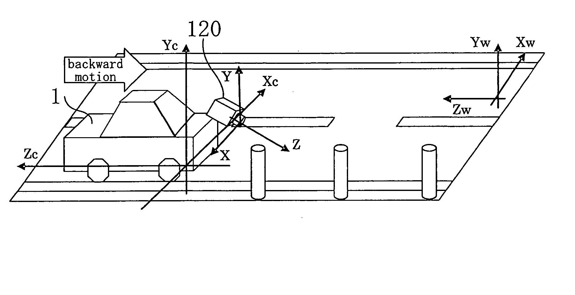
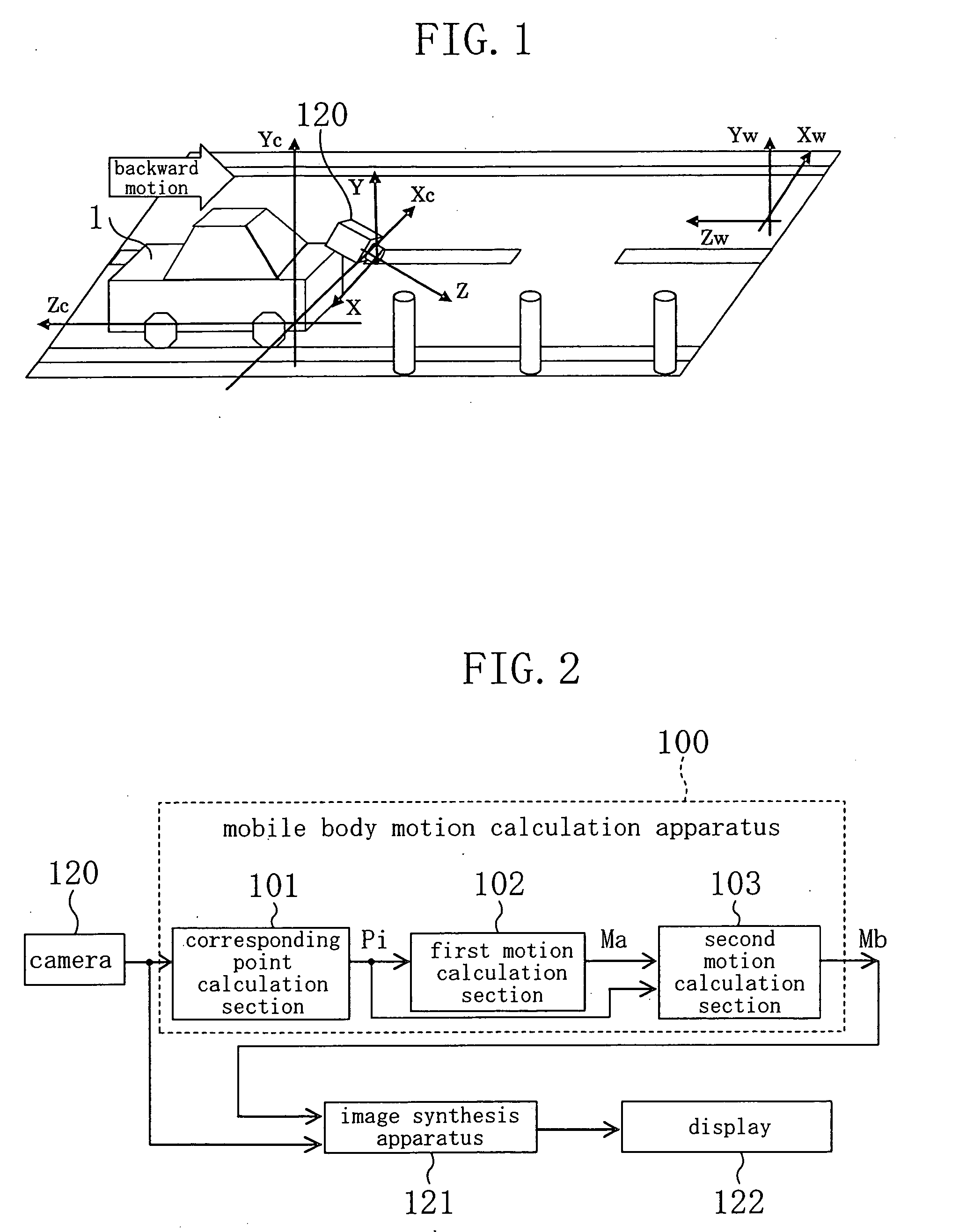
[0070] In a first embodiment of the present invention, a vehicle on which a camera is mounted is employed as an example of a mobile body, and a motion of the vehicle is obtained using images of a rear view behind the vehicle which are captured by the camera.

[0071]FIG. 1 is a diagram showing a situation in the first embodiment. As shown in FIG. 1, a vehicle 1 (mobile body) is provided with a camera 120 which is mounted at a rear portion thereof and is used to capture images of a rear surrounding thereof. The camera 120 captures images of the rear surrounding of the vehicle and outputs a sequence of images.

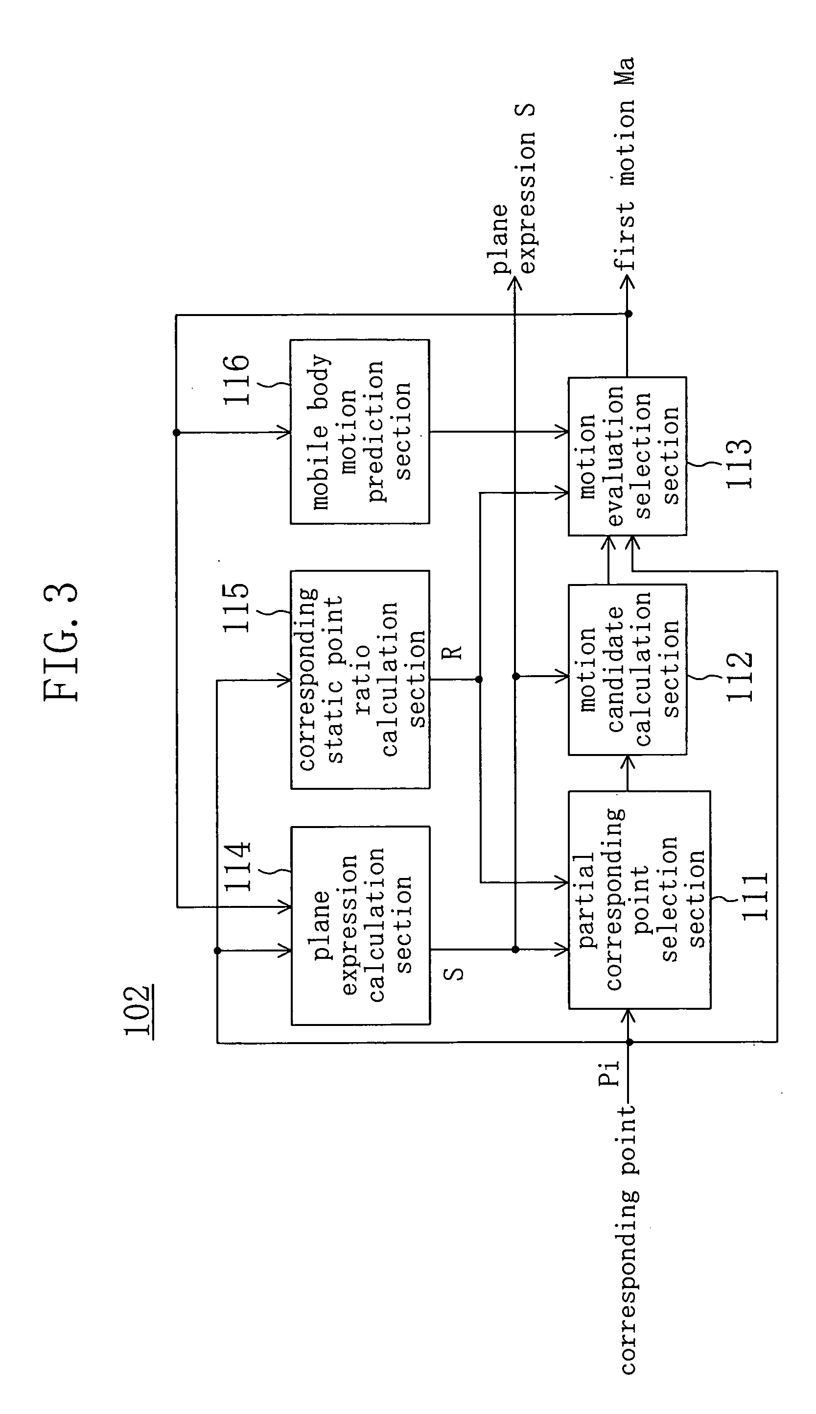
[0072]FIG. 2 is a block diagram showing a structure including a mobile body motion calculation apparatus of the first embodiment. In FIG. 2, 100 indicates a mobile body motion calculation apparatus which calculates a motion of the vehicle 1 from the images captured by the camera 120; 121 indicates an image synthesis apparatus which generates a synthesized image in which the image ...

second embodiment

[0175] In a second embodiment of the present invention, a mobile body motion calculation apparatus constructed in a manner similar to that of the first embodiment is combined with a navigation apparatus to construct a navigation system. It is here assumed that the navigation apparatus has a function of measuring a current location using a radio wave from an artificial satellite and a function of displaying the current location or guidance to a destination using the current location and map information.

[0176]FIG. 16 is a diagram showing a structure of a navigation system including a mobile body motion calculation apparatus according to the second embodiment of the present invention. In FIG. 16, components common to FIGS. 2 and 3 are indicated with the same reference numerals and will not be explained in detail.

[0177] In FIG. 16, a navigation apparatus 130 comprises a positional information obtaining section 131, a positional information calculation section 132, an image synthesis s...


PUM


Abstract

In a mobile body motion calculation apparatus (100), a corresponding point calculation section (101) calculates corresponding points between images captured by a camera 120. A first motion calculation section (102) calculates a first motion (Ma) of a mobile body using the corresponding points, assuming a predetermined plane in the images. A second motion calculation section (103) calculates a second motion (Mb) using the first motion (Ma) and the corresponding points.

Description

TECHNICAL FIELD [0001] The present invention relates to a technique of calculating a motion of a mobile body. More particularly, the present invention relates to a technique of calculating a motion of a mobile body in three-dimensional space using an image captured by a camera mounted on the mobile body itself. BACKGROUND ART [0002] A motion of a mobile body, such as a vehicle, a mobile robot or the like, is usually calculated by any of two methods: a method of using a sensor which detects a rotation of a wheel, an angle of a steered wheel, an acceleration, an angular acceleration or the like; and a method of using images of a surrounding of a mobile body which are captured by a camera mounted on the mobile body. [0003] A method of using a sensor which detects a rotation of a wheel or an angle of a steered wheel is advantageously stable in because of a small error and less frequent failure of detection in certain circumstances, such as a flat and dry road surface or the like. Howeve...

Claims


Application Information

Patent Timeline
Patent Type & Authority Applications(United States)
IPC IPC(8): H04N7/18G05D1/02G06T1/00G06T7/00G06T7/20
CPCB60R1/00B60R2300/30B60R2300/302B60R2300/305B60R2300/307G06T7/2033B60R2300/8086B60R2300/8093G05D1/0253G05D2201/0213G06T7/0071B60R2300/806G06T7/579G06T7/246G06V20/56
Inventor NOBORI, KUNIOSATO
Owner PANASONIC INTELLECTUAL PROPERTY CORP OF AMERICA
Why Eureka
Try Eureka