Cam mechanism of a zoom lens

Inactive Publication Date: 2006-03-16
HOYA CORP
View PDF5 Cites 14 Cited by
  • Summary
  • Abstract
  • Description
  • Claims
  • Application Information

AI Technical Summary

Benefits of technology

[0006] The present invention provides a cam mechanism of a lens barrel which includes a cam ring, wherein a plurality of cam grooves having different reference cam diagrams are formed on the cam ring to move a plurality of linearly guided movable members (e.g., movable frames which support lens groups) in an optical axis direction by rotation of the cam ring, and wherein the degree of flexibility in the range of movement of each linearly guided movable member can be increased while miniaturization of the zoom lens and multiplication of variable power ratio of the zoom lens can be achieved.
[0007] According to an aspect of the present invention, a cam mechanism of a zoom lens is provided, including a cam ring including a plurality of cam grooves having different reference cam diagrams on at least one of inner and outer peripheral surfaces of the cam ring; and a plurality of movable frames which include a plurality of cam followers respectively engaged in the plurality of cam grooves, the movable frames being guided linearly in an optical axis direction. Each of the plurality of cam grooves includes a zooming section for moving an associated one of the plurality of movable frames between a wide-angle extremity position and a telephoto extremity position in the optical axis direction in accordance with rotation of the cam ring, and a zooming-range-extremity stop section, communicatively connected to one end of the zooming section, for preventing the associated one of the movable frames from moving in the optical axis direction from one of the wide-angle extremity position and the telephoto extremity position when the cam ring rotates within the zooming-range-extremity stop section.
[0014] According to the present invention, a cam mechanism of a lens barrel which includes a cam ring is provided, wherein a plurality of cam grooves having different reference cam diagrams are formed on the cam ring to move a plurality of linearly guided movable members (e.g., movable frames which support lens groups) in an optical axis direction by rotation of the cam ring, and wherein the degree of flexibility in the range of movement of each linearly guided movable member can be increased while miniaturization of the zoom lens and multiplication of variable power ratio of the zoom lens can be achieved.

Problems solved by technology

However, such a cam groove design makes it impossible for two optical elements (e.g., two lens elements), adjacent to each other in the optical axis direction of the zoom lens, to be brought close to each other until the closest limit at the wide-angle extremity or the telephoto extremity of the zoom lens, because the moving amounts of the two optical elements for the wide-angle marginal section and the telephoto marginal section, respectively, must be taken into account if each cam groove is provided at the opposite ends thereof with the wide-angle marginal section and the telephoto marginal section, respectively.

Method used


Image

  • Cam mechanism of a zoom lens
  • Cam mechanism of a zoom lens
  • Cam mechanism of a zoom lens

Examples


Embodiment Construction

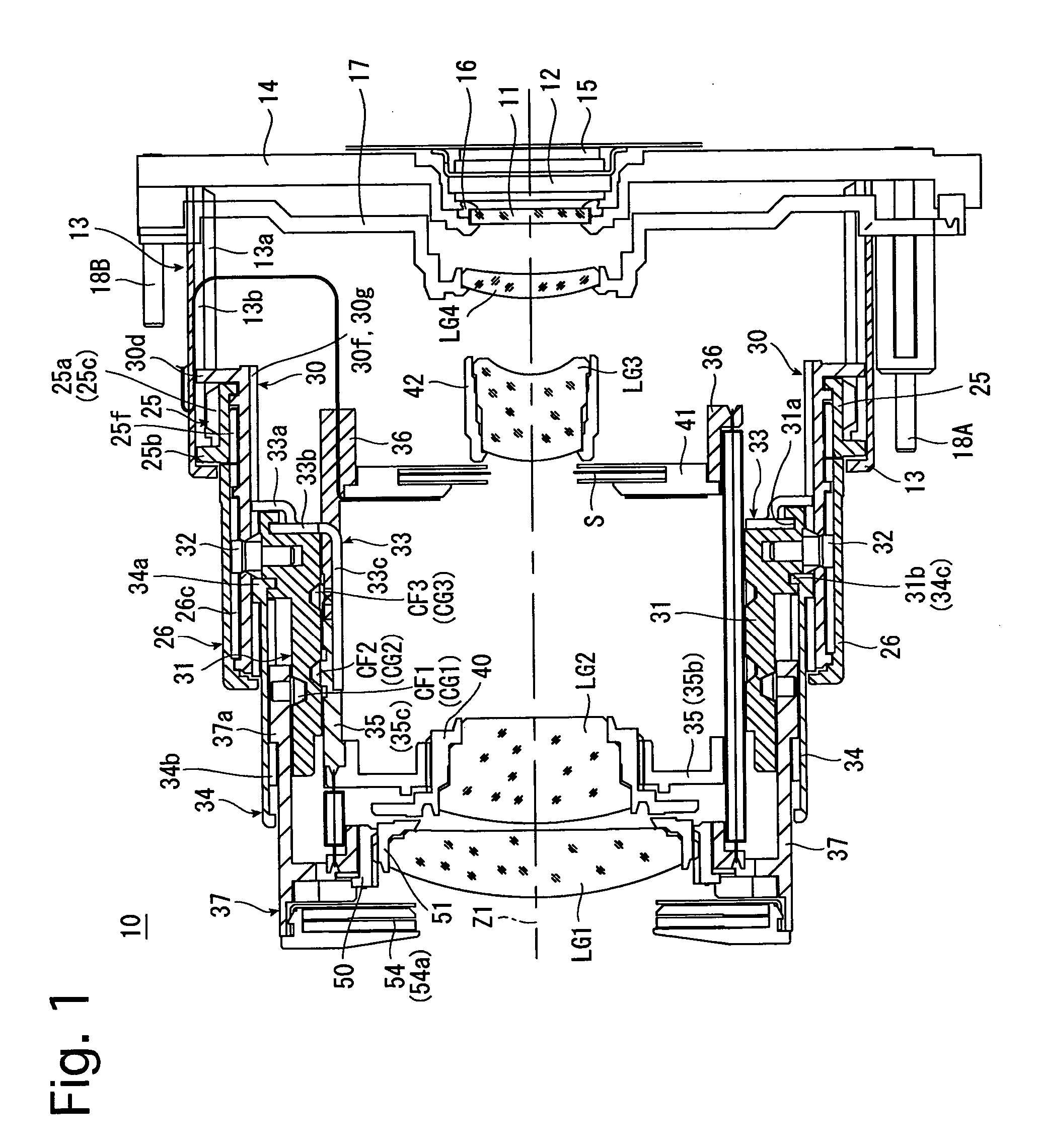
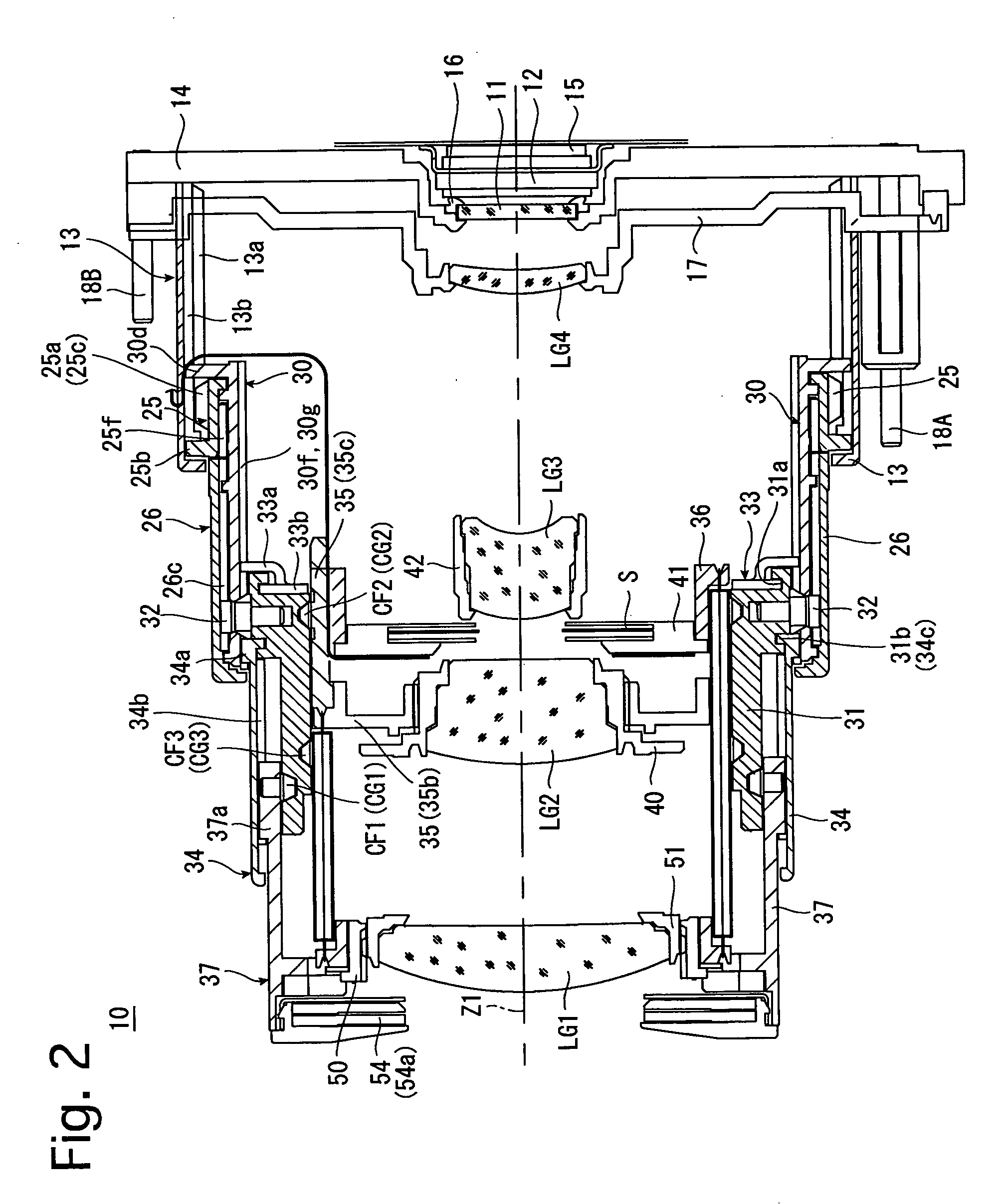
[0054]FIGS. 1 through 3 show an embodiment of a zoom lens according to the present invention in different states. FIG. 1 shows a state of the zoom lens 10 at the wide-angle extremity, FIG. 2 shows a state of the zoom lens 10 at the telephoto extremity, and FIG. 3 shows a state of the zoom lens in a retracted position (fully retracted position). The zoom lens 10 is incorporated in a digital camera (the camera body thereof is not shown in the drawings). As shown in FIGS. 1 and 2, the photographing optical system of the zoom lens 10 in a ready-to-photograph state of the zoom lens 10 consists of a first lens group LG1, a second lens group (front optical element) LG2, a shutter S, a third lens group (rear optical element) LG3, a fourth lens group LG4, a low-pass filter (optical filter) 11, and a CCD image sensor (solid-state image pick-up device) 12. The first lens group LG1, the second lens group LG2 and the third lens group LG3 are driven along a photographing optical axis Z1 in a pred...


PUM


Abstract

A cam mechanism of a zoom lens, includes a cam ring including cam grooves having different reference cam diagrams on at least one of inner and outer peripheral surfaces of the cam ring; and movable frames which include cam followers respectively engaged in the cam grooves, the movable frames being guided linearly in an optical axis direction. Each of the cam grooves includes a zooming section for moving an associated one of the movable frames between a wide-angle extremity position and a telephoto extremity position in the optical axis direction in accordance with rotation of the cam ring, and a zooming-range-extremity stop section, communicatively connected to one end of the zooming section, for preventing the associated one of the movable frames from moving in the optical axis direction from one of the wide-angle extremity position and the telephoto extremity position even when the cam ring rotates.

Description

BACKGROUND OF THE INVENTION [0001] 1. Field of the Invention [0002] The present invention relates to a zoom lens, more particularly to a cam mechanism, incorporated in the zoom lens, for moving optical elements such as lens groups. [0003] 2. Description of the Related Art [0004] In conventional zoom lenses, it is often the case that a cam ring incorporated therein is provided on an inner peripheral surface or an outer peripheral surface thereof with a set of cam grooves for moving a linearly guided optical element such as a lens group. Each of these cam grooves is usually provided, at the opposite ends of a photographing section (zooming section) thereof between a wide-angle extremity position and a telephoto-extremity position, with an adjustment marginal section which allows the associated cam follower to move beyond a predetermined position thereof at the wide-angle extremity of the zoom lens (hereinafter referred to as a wide-angle marginal section) and another adjustment margin...

Claims


Application Information

Patent Timeline
IPC IPC(8): G02B7/02G02B7/10
CPCG02B7/102
Inventor ISHIZUKA, KAZUNORISUZUKI, TOSHIHARU
Owner HOYA CORP
Why Eureka
Try Eureka