Vise assembly and bench circular sawing machine

Active Publication Date: 2009-11-05
MAKITA CORP
View PDF11 Cites 1 Cited by
  • Summary
  • Abstract
  • Description
  • Claims
  • Application Information

AI Technical Summary

Benefits of technology

[0014]Advantageous effects of some aspects and embodiments of the present invention as described above are as follows:
[0015]With the configurations according to the first, the sixth and the seventh aspects of the present invention, the degree of flexibility in selecting the holding positions can be increased and thus the ease of use can be improved.
[0016]According to the second aspect of the present invention, the advantage of the configuration according to the first aspect can be brought about as well, and besides, flexibility in selecting the holding positions can be expanded vertically, so that the ease of use can be expected to be further increased. In particular, since the second arm is configured to be movable upward and downward, the length of the clamping rod can be designed to be shorter so that upward protrusion of the assembly can be reduced and the possibility of danger of hitching something or catching an operator's hand on such protrusion during operation can be reduced.
[0017]According to the third aspect of the present invention, the advantage of the configuration according to the first or the second aspects can be enjoyed as well, and besides, by horizontally rotating or swiveling the first arm together with the support rod as being horizontally rotated, a finer adjustment of the horizontal holding position can be performed in combination of the horizontal rotation of the second arm. Therefore, flexibility in selection of the horizontal holding positions can be increased further.
[0018]According to the fourth aspect of the present invention, the advantage of the configuration according to any one of the first to the third aspects can be enjoyed as well, and besides, the holding position can be changed easily with the thumb screw.
[0019]According to the fifth aspect of the present invention, the advantage of the configuration according to the fourth aspect can be drawn as well, and besides, an undesired slip of the slide rod after holding down a workpiece can be prevented effectively, resulting in increasing reliability of holding the workpiece.

Problems solved by technology

In this way, the range of selection of the holding position of the bench screw is inconveniently limited, which would in some instances require the vise assembly to change in its installation position; for example, when the main body is to be tilted sideways to perform a bevel cut, the vise assembly should be mounted on the side opposite to that to which the main body is tilted so as to avoid interference with the main body in operation.
Thus, this limitation would impair the ease of use.

Method used


Image

  • Vise assembly and bench circular sawing machine
  • Vise assembly and bench circular sawing machine
  • Vise assembly and bench circular sawing machine

Examples


Embodiment Construction

[0028]Exemplary embodiments of the present invention will be described hereinafter with reference to the accompanying drawings.

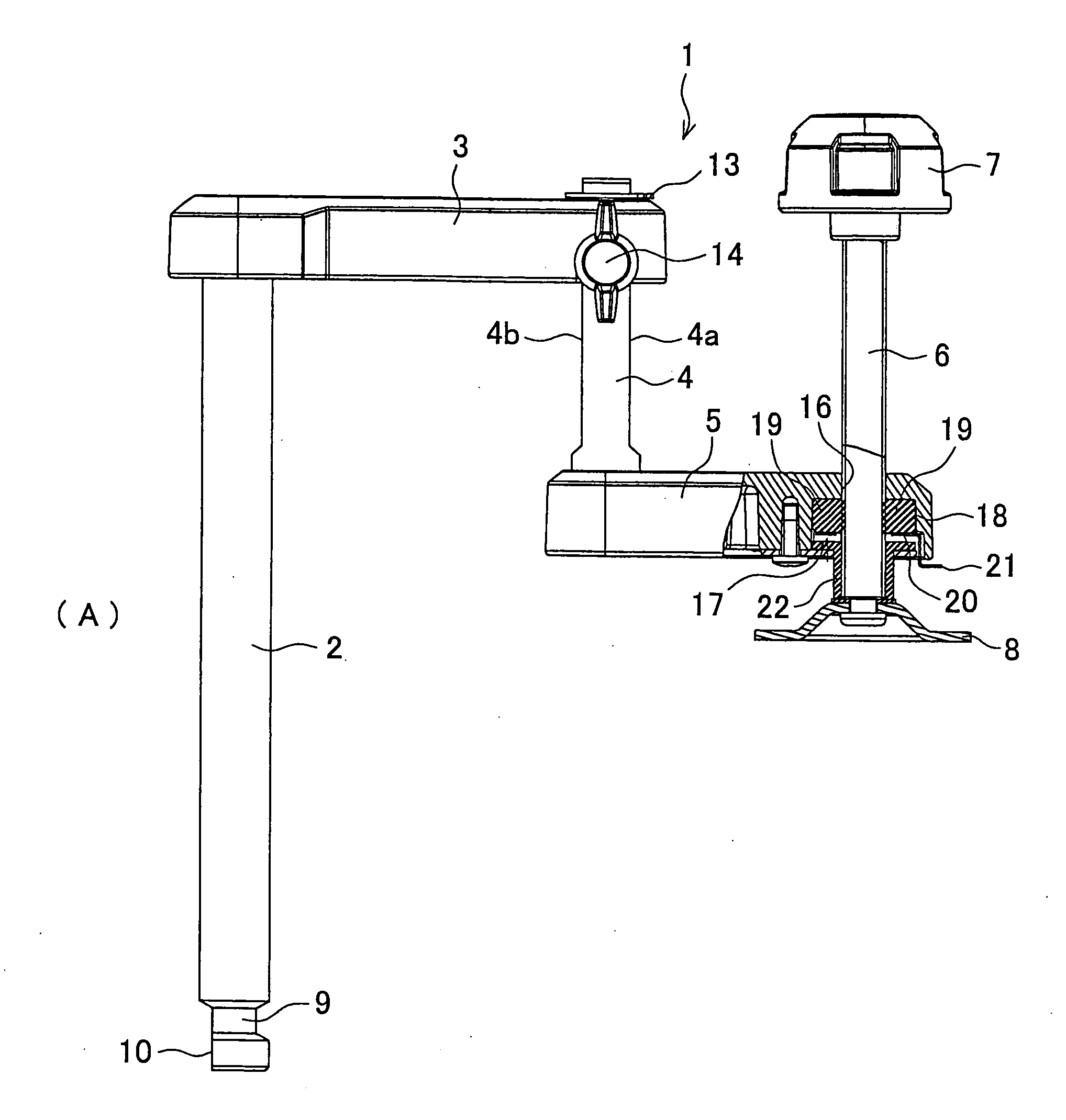
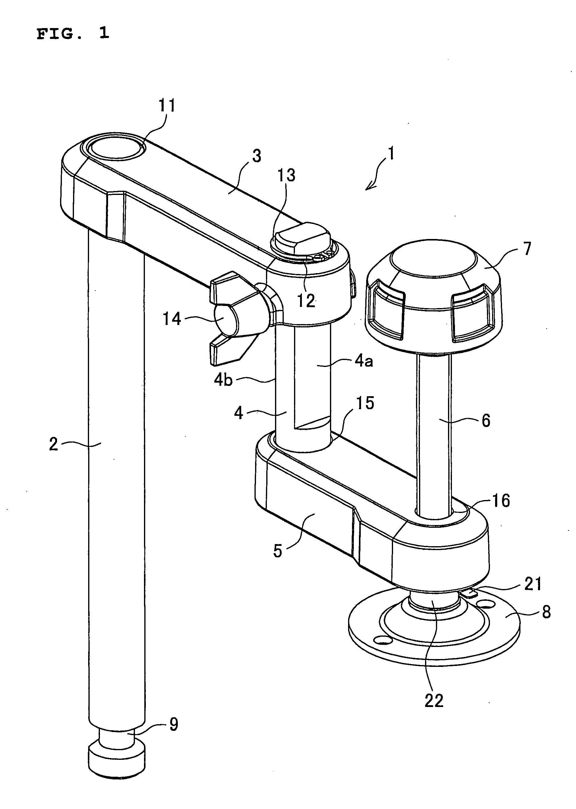
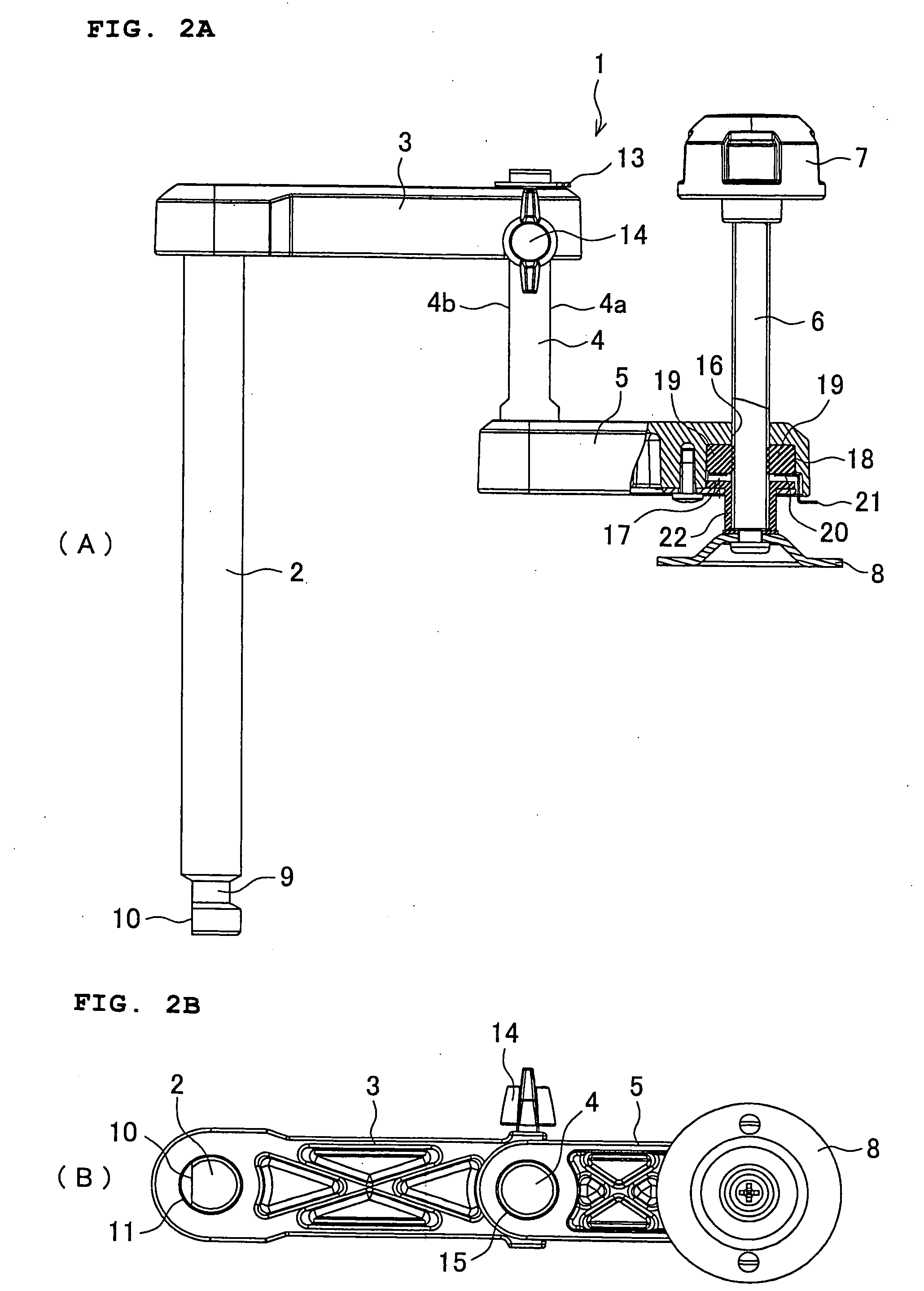
[0029]Referring now to FIGS. 1 and 2, a vise assembly 1 includes a support rod 2 vertically disposed and mounted with its lower end portion inserted in an opening provided in a base of a bench circular sawing machine that will be described later, a first arm 3 having one end portion connected to an upper end portion of the support rod 2 and projecting horizontally, a second arm 5 having one end portion connected to the other end portion of the first arm 3 via a slide rod 4 and projecting horizontally, and a clamping rod 6 disposed vertically at the other end portion of the second arm 5 and having an operation knob 7 disposed at an upper end thereof, and a disk-shaped clamping shoe 8 disposed at a lower end thereof.

[0030]The support rod 2 is a member shaped like a shaft having a circular cross section, and the lower end portion of the support rod 2 comprises ...


PUM


Abstract

A vise assembly includes a support rod standing on a base of a bench circular sawing machine, a first arm connected to the support rod and projecting frontward, a second arm of which a rear end portion is connected to a front end portion of the first arm in such a manner that the second arm is horizontally swingable and capable of being retained at any angular position, and a clamping rod disposed at a front end portion of the second arm, configured to be movable upward and downward, and capable of holding a workpiece placed in a cutting region. Optionally, the rear end portion of the second arm is movable upward and downward and capable of being retained at any vertical position.

Description

BACKGROUND OF THE INVENTION[0001]This application claims the entire benefit of Japanese Patent Application Number 2008-118914 filed on Apr. 30, 2008, the entirety of which is incorporated by reference.TECHNICAL FIELD[0002]This invention relates to a vise assembly for use in holding a workpiece in a bench circular sawing machine, and also to a bench circular sawing machine in which the vise assembly is provided.BACKGROUND ART[0003]In a bench circular sawing machine, its main body including a motor-driven rotary saw blade is provided above a base and configured to be movable upward and downward so that a workpiece placed on (or over) the base can be cut by lowering the main body. A vise assembly is used to hold the workpiece on the base during the cutting operation. Among vise assemblies of various types known in the art, such a vise assembly as disclosed for example in JP 6-71604 A comprises a vertical bar (support rod), a horizontal bar (arm) attached to the vertical bar and configu...

Claims


Application Information

Patent Timeline
IPC IPC(8): B25B1/20B27B5/18
CPCB23D47/04B25B1/103B27B5/29B25B5/006B25B5/10B25B1/125Y10T83/7697
Inventor YAMAMURA, GOHKANI, TOSHIYUKI
Owner MAKITA CORP
Why Eureka
Try Eureka