System and method for a wireless mesh network

a wireless mesh network and wireless technology, applied in the field of wireless communication, can solve the problems of inability to exercise control over a system, inability to detect a condition at a remotely located position or in a remote location, and inability to monitor and control devices in areas where remote sensors and controllers are positioned miles away from the central control area instead of feet,

Inactive Publication Date: 2006-03-16
NIVIS
View PDF50 Cites 119 Cited by
  • Summary
  • Abstract
  • Description
  • Claims
  • Application Information

AI Technical Summary

Problems solved by technology

The monitoring and controlling of devices located remotely from a central location has historically provided many challenges.
The ability to detect a condition at a remotely located position or to exercise control over a system (such as turning a device off and on) from a central location has oftentimes been limited by the distance of the central control location from the device that is monitored or controlled.
However, hardwired monitoring and controlling of devices in areas wherein the remotely located sensors and controllers are positioned miles away from the central control area instead of feet becomes impractical due to the inability to communicate electrical control signals between the central control room and the remotely located sensor or controller.
However, a problem with this configuration is that data is collected from an individual meter in the geographic area of meters when the utility personnel comes within the broadcast range of the individual meters at each location.
While this is an improvement over utility personnel having to physically inspect and read each individual meter, the problem of this configuration is that it still relies on a human for data collection.
However, difficulties in communicating the data across the same line that carries high voltage electricity has encountered many difficulties, thereby making this approach less practical.
So this solution is limited, at best.
However, the problem with this proposal is that it involves other parties, such as a telephone company, for implementing the system and also suffers from a lack of priority.
For example, when the homeowner is using the telephone line, the modem in the meter cannot acquisition the line.
Requiring utility consumers to procure second telephone lines for meter communication is impracticable and still suffers from the fact that reliance on other parties is required.
However, these wireless communication proposals suffer from several drawbacks and inabilities.
For example, while a number of meters may communicate with each other due to the relatively close proximity of their respective locations, getting the data back to the central monitoring and control location has proven to be yet another obstacle.
This limitation has previously meant that a data gathering device must be located within the short communication range of each wireless transceiver, or that separate repeaters must be used to repeat the data from the remotely located meters to the portals so that each meter can communicate its data up the chain to the central location.
These types of solutions have also been plagued by communication problems, including bottlenecks and breakdowns in the chain.
Battery and memory concerns render some remotely located meters inaccessible, thereby resulting in a system where all meters within a given geographical area cannot be included in the communication network.
Consequently, the inability to network the various geographically distributed meters into an integrated system wherein data can be monitored and also controlled from a central location has caused some of the inferior solutions discussed above to be implemented, such as requiring meter reading personnel to drive through areas where meters are equipped with limited broadcast capabilities.
Moreover, the prohibitive costs associated with installing a great number of portals and / or repeaters in an area so that each individual utility meter can be networked has stymied the development of wireless automatic meter reading networks.
As a result, a heretofore unaddressed need exists to overcome the deficiencies and shortcomings described above.

Method used


Image

  • System and method for a wireless mesh network
  • System and method for a wireless mesh network
  • System and method for a wireless mesh network

Examples


Embodiment Construction

[0033] In addition to the drawings discussed above, this description describes one or more embodiments as illustrated in the above-referenced drawings. However, there is no intent to limit this disclosure to a single embodiment or embodiments that are disclosed herein. On the contrary, the intent is to cover all alternatives, modifications, and equivalents included within the spirit and scope of this disclosure and as defined by the appended claims.

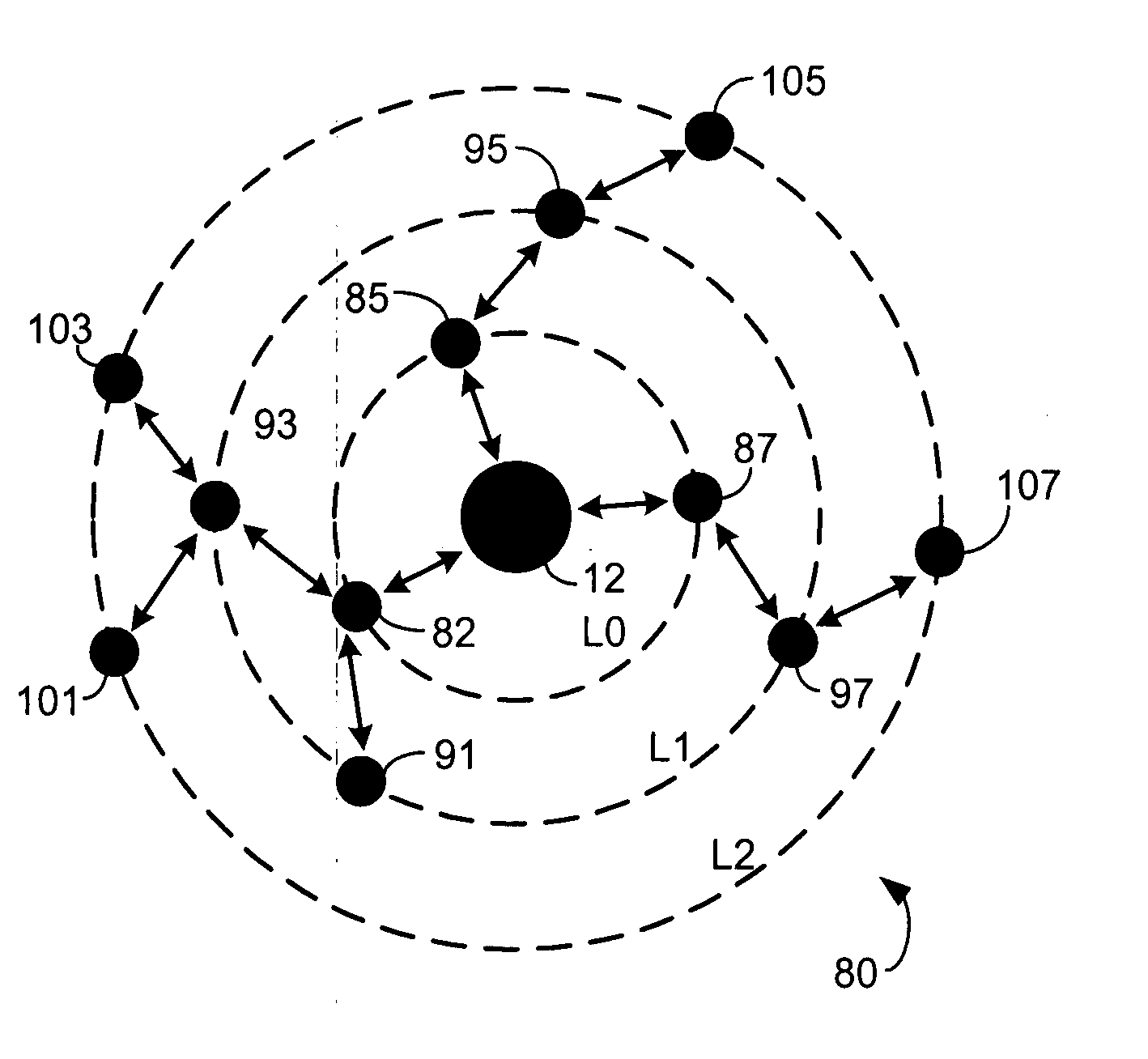
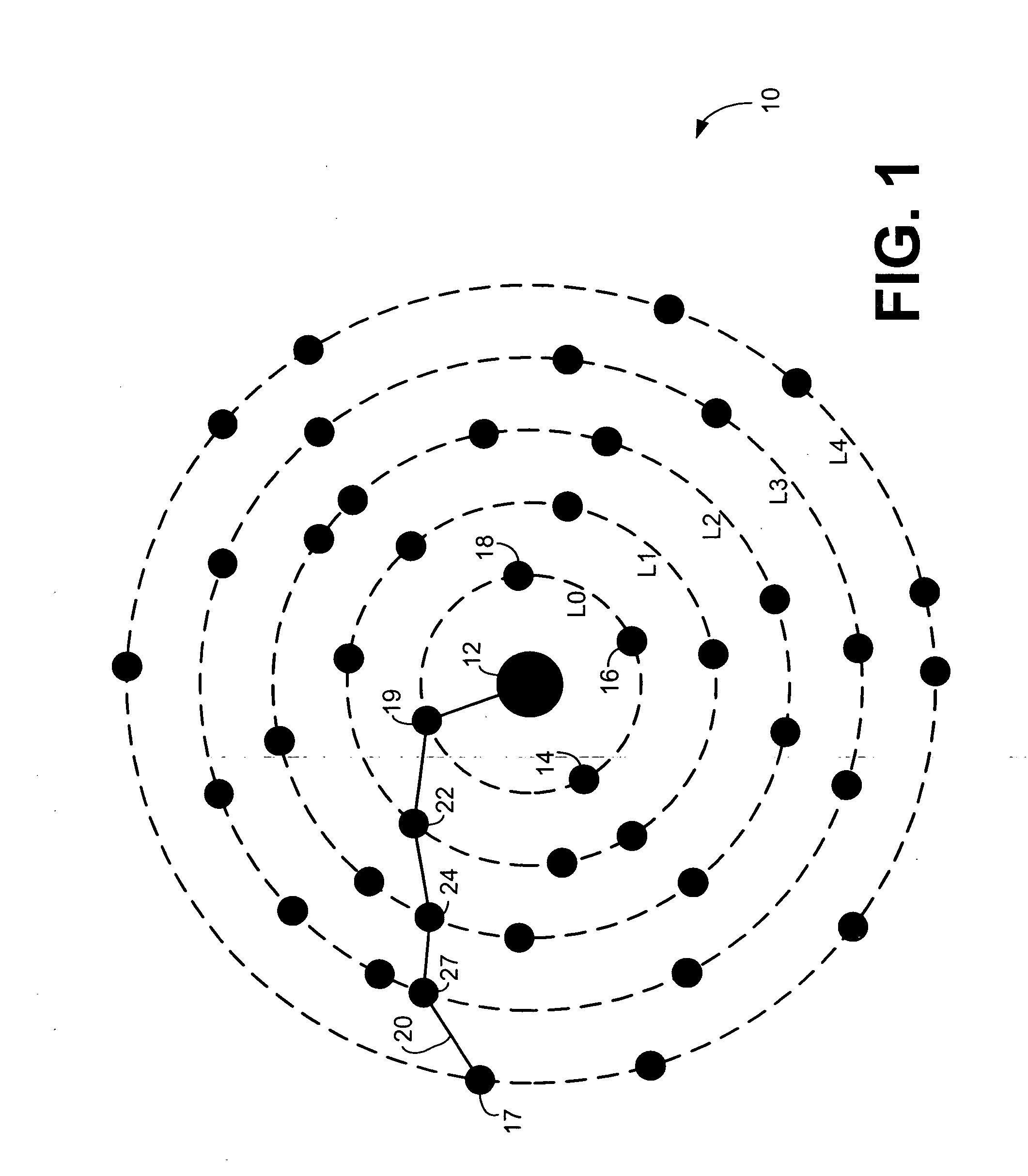
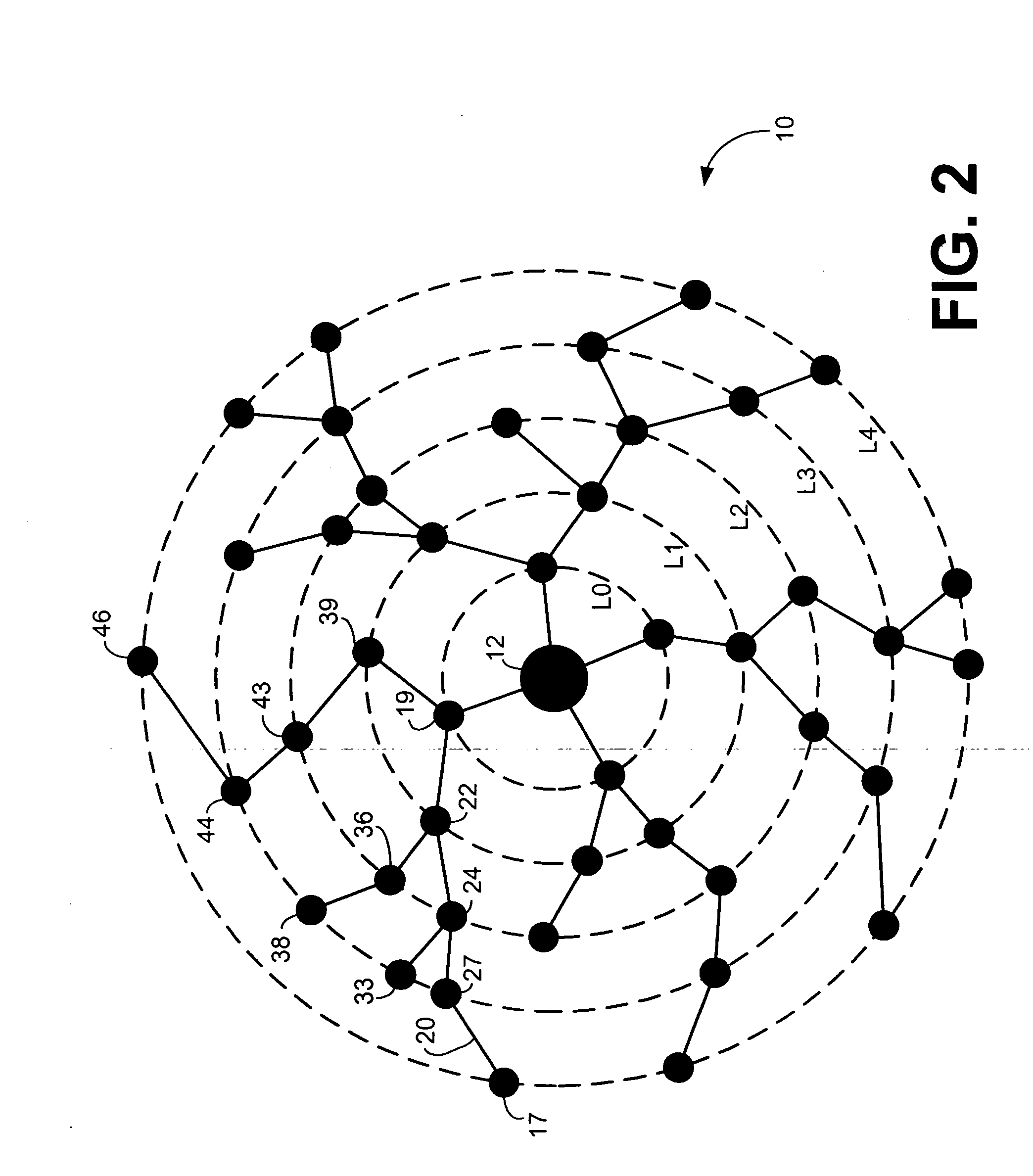
[0034] A system for an access node coupled to a computer to wirelessly communicate with a plurality of disparately located radio nodes each coupled to a meter or other sensor is provided. The radio nodes within the communication range of the access node orient onto a first logical layer to directly communicate with the access node. Additional radio nodes beyond the communication range of the access node indirectly communicate with the access node by detecting communications from radio nodes on lower logical layers that are closer to the ...


PUM


Abstract

A system for an access node coupled to a computer to wirelessly communicate with a plurality of disparately located radio nodes each coupled to a meter or other sensor is provided. The radio nodes within the communication range of the access node orient onto a first logical layer to directly communicate with the access node. Additional radio nodes beyond the communication range of the access node indirectly communicate with the access node by detecting communications from radio nodes on lower logical layers that are closer to the access node and selecting a radio node of the detected radio nodes to be a repeater node. The selected repeater node has available memory capacity and a suitable power number to qualify as a repeater, which may periodically change. Sensed data is directly or indirectly communicated to the access node for further communication to a backend system computer.

Description

FIELD OF THE INVENTION [0001] This invention generally pertains to wireless communications and, more particularly, to a system, method, and apparatus for meshing a network of wireless devices. BACKGROUND OF THE INVENTION [0002] The monitoring and controlling of devices located remotely from a central location has historically provided many challenges. The ability to detect a condition at a remotely located position or to exercise control over a system (such as turning a device off and on) from a central location has oftentimes been limited by the distance of the central control location from the device that is monitored or controlled. For example, monitoring and controlling devices within a manufacturing facility or a power plant may be accomplished by hardwiring the sensors and controllers with monitors and controllers in the central control room that may be only a few hundred feet away. However, hardwired monitoring and controlling of devices in areas wherein the remotely located ...

Claims


Application Information

Patent Timeline
Patent Type & Authority Applications(United States)
IPC IPC(8): H04L12/26
CPCG01D21/00H04B7/026H04W40/04H04W40/10Y02B60/50H04W52/04H04W52/46H04W84/18H04W40/22
Inventor RATIU, OVIDIUCHILOM, MARIUS OVIDIUTICUS, ION
Owner NIVIS
Why Eureka
Try Eureka