
Syncronization signal detection apparatus and synchronization signal detection method

a detection apparatus and signal technology, applied in the field of synchronization signal detection apparatus and synchronization signal detection method, can solve the problems of difficult to recognize the section of each frame, data cannot be normally reproduced, and the reading of digital data cannot be appropriately reproduced

Inactive Publication Date: 2006-03-16
SONY CORP
View PDF5 Cites 16 Cited by
  • Summary
  • Abstract
  • Description
  • Claims
  • Application Information

AI Technical Summary

Benefits of technology

The present invention provides a synchronization signal detection apparatus and method that can detect and synchronize with signals in a video or audio frame. The apparatus includes a synchronization signal detection means and an interpolation means to generate a reproducing synchronization signal when a synchronization signal is not detected in a frame. The apparatus also includes a judgment means to determine if the synchronization signal is at normal timing and a resynchronization means to output the synchronization signal as the reproducing synchronization signal based on the judgment result. The technical effect of this invention is to enable accurate synchronization of video or audio frames with signals in a more efficient and reliable manner.

Problems solved by technology

Then, it becomes difficult to recognize the section of each frame consequently, and there is the possibility that the read digital data cannot be reproduced appropriately.
However, in the case where the omission or the shift described above is continuous, there is the possibility that a difference is produced between the reproducing sync (namely the interpolation sync here) and an originally expected sync position for data reproduction, and that the data cannot be normally reproduced.
However, on the basis of the above description, according to the conventional forward guard operation, the resynchronization of the sync is not performed until the interpolation sync has been interpolated by the number of times corresponding to the forward guard times. Consequently, even if each time of the frame sync re-detected in the way described above is detected at the appropriate timing, the resynchronization with the sync cannot be immediately performed.

Method used


Image

  • Syncronization signal detection apparatus and synchronization signal detection method
  • Syncronization signal detection apparatus and synchronization signal detection method
  • Syncronization signal detection apparatus and synchronization signal detection method

Examples


Embodiment Construction

[0051] In the following, a case where a synchronization signal detection apparatus of the present invention is applied to a disc reproducing apparatus capable of reproducing digital data recorded on a disc recording medium is exemplified.

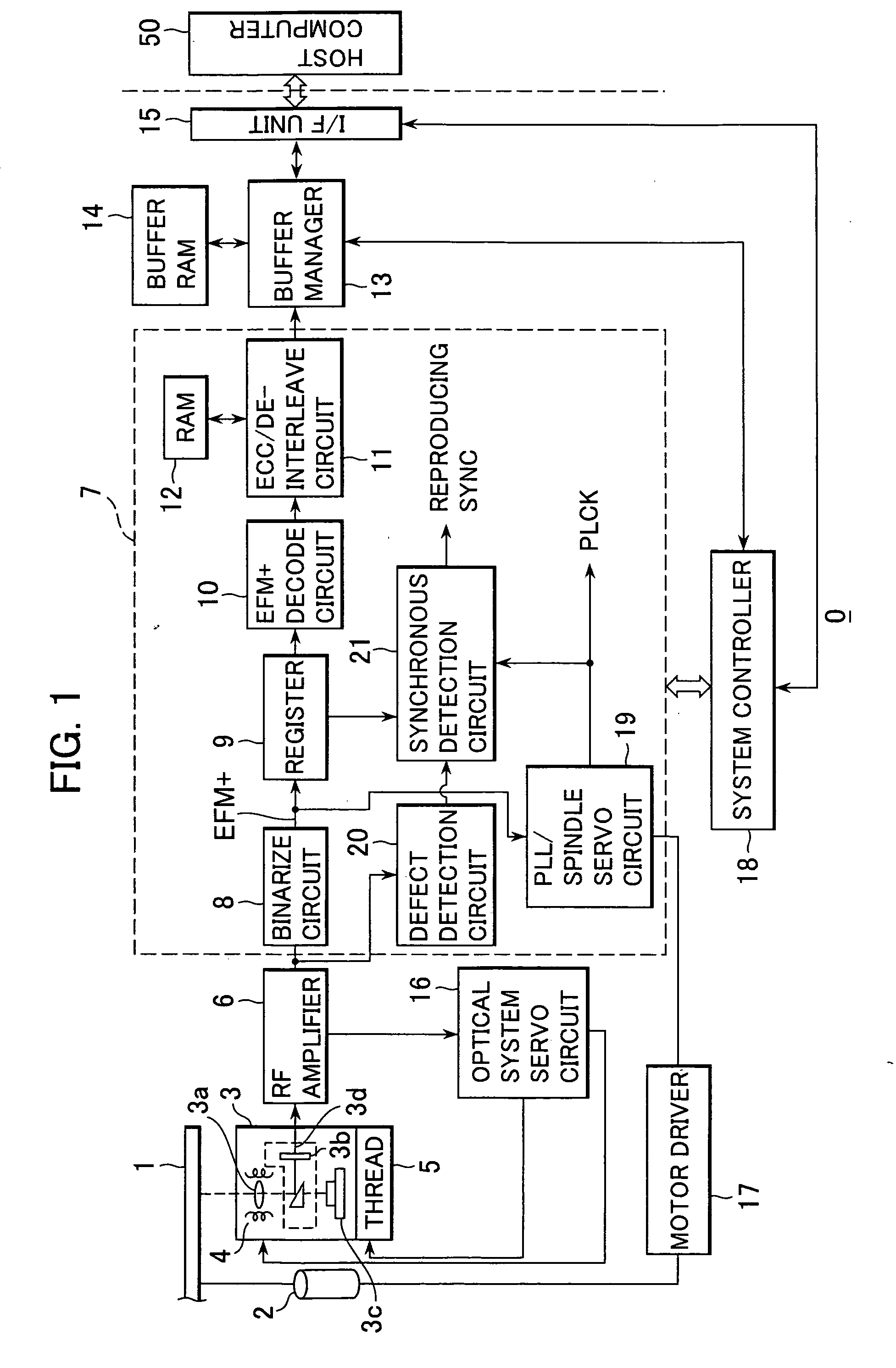
[0052]FIG. 1 shows the configuration of a disc reproducing apparatus 0, to which the synchronization signal detection apparatus as an embodiment of the present invention is applied. The disc reproducing apparatus 0 shown in this figure has a configuration capable of reproducing data correspondingly to a recordable disc such as a DVD-R, a DVD-RW and a DVD-RAM as an optical disc of a DVD format.

[0053] In this figure, a disc 1 is driven to rotate by a spindle motor 2 at the time of reproduction operation in accordance with a predetermined rotation control method such as Constant Angular Velocity (CAV), Constant Linear Velocity (CLV) and Zoned Constant Linear Velocity (ZCLV). Then, the read out of pit data recorded in a track on the disc 1 and the wob...


PUM

PropertyMeasurementUnit
defect stateaaaaaaaaaa
timeaaaaaaaaaa
Velocityaaaaaaaaaa

Abstract

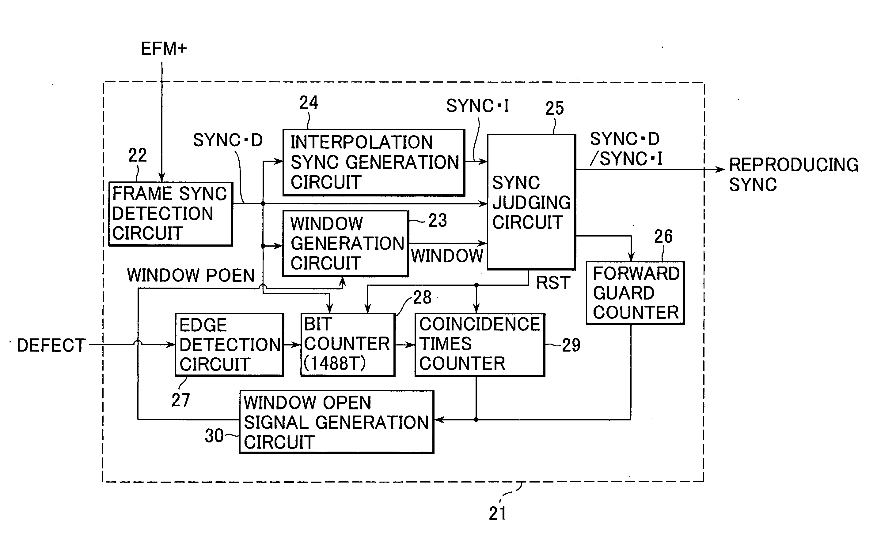
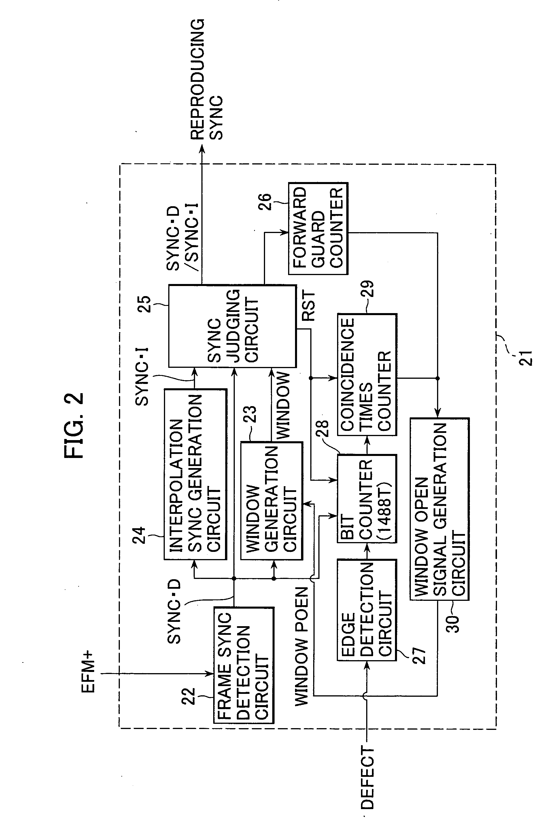
A synchronization signal detection apparatus and a synchronization signal detection method for improving the reading performance of an input signal after the dissolution of a defect state or the like. Under a predetermined condition after no synchronization signals from an input signal have been detected in predetermined detection periods and the interpolation of synchronization signals has been started, the judgment about whether each of the synchronization signals detected from the input signal continuously is detected at normal timing or not is performed. Then, according to the judgment result, the resynchronization operation of the synchronization signals detected from the input signal and reproducing synchronization signals is performed. Thereby, the state in which the synchronization signals having different timing from originally expected timing are used owing to the interpolation of synchronization signals can be immediately dissolved.

Description

TECHNICAL FIELD [0001] The present invention relates to a synchronization signal detection apparatus and a synchronization signal detection method in the synchronization signal detection apparatus. BACKGROUND ART [0002] Digital data which has a predetermined format and has been modulated by a record coding modulation such as Eight to Fourteen Modulation (EFM) and EFM+ is recorded on an optical disc such as a compact disc (CD) and a digital versatile disc (DVD). Then, in the above-mentioned format, the digital data is recorded on the disc in the sequence by the frame including a predetermined sync pattern. [0003] Accordingly, on the side of an apparatus for performing the reproduction of the optical disc, a synchronous detection circuit for detecting the predetermined sync pattern (frame synchronization signal) included in read digital data is provided to recognize the section of each frame. Then, the digital data read from the optical disc can be suitably reproduced. [0004] Now, in ...

Claims


Application Information

Patent Timeline
Patent Type & Authority Applications(United States)
IPC IPC(8): H04L7/00G11B20/14G11B20/18H04N5/08H04N5/93
CPCH04N5/08G11B27/10G11B20/14
Inventor OONO, YUUKOTADA, KOJI
Owner SONY CORP
Learn More