Data processing apparatus and control method thereof

a data processing and control method technology, applied in the field of video data processing, can solve the problems of limited number of processing units that can be mounted therein, content that can only be serviced, and structure cannot meet a request, so as to achieve the effect of increasing the size of the apparatus

Active Publication Date: 2006-03-16
CANON KK
View PDF11 Cites 21 Cited by
  • Summary
  • Abstract
  • Description
  • Claims
  • Application Information

AI Technical Summary

Problems solved by technology

However, when a plurality of users access one camera, such a structure can only meet a request from a user who has first priority.
However, in such a case, the contents that can be serviced may be restricted by the number of such processing units.
However, a network camera server, etc., which assumes the function on the image-taking side of a video delivery system is generally required to be smaller in size and the number of processing units that can be mounted therein is limited to the areas of the substrate / chip or heat value, etc.
For that reason, there is a problem that the number of such processing units is actually limited.
For this reason, there is a problem that a considerable difference is produced between the time at which the image is taken and the time at which the image is reproduced.
This problem is serious in the case where motion images are taken and those motion images are used at remote places for monitoring purposes, etc., at a plurality of locations with primary importance placed on the real-time nature by a plurality of users.
Therefore, the number of users to whom the images can be delivered simultaneously is significantly limited.
For this reason, there is a problem that image quality obviously deteriorates compared to a case where non-encoded or non-converted images are processed.
Furthermore, the technology described in Japanese Patent Laid-Open No. 2004-151167 is limited to a case where a limited display device (LCD) such as a cellular phone is used, and cannot be applied to an unspecified majority of types of displays.

Method used


Image

  • Data processing apparatus and control method thereof
  • Data processing apparatus and control method thereof
  • Data processing apparatus and control method thereof

Examples


first embodiment

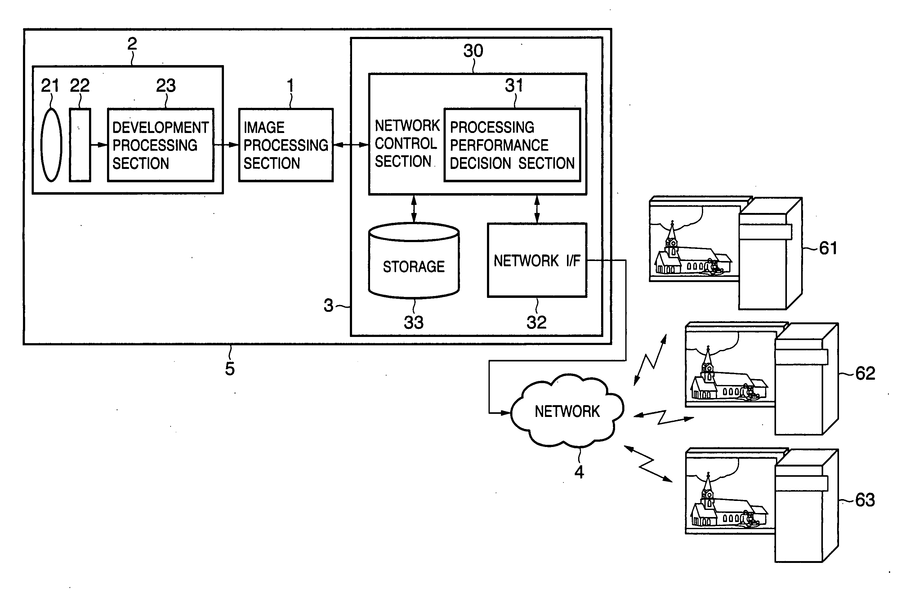
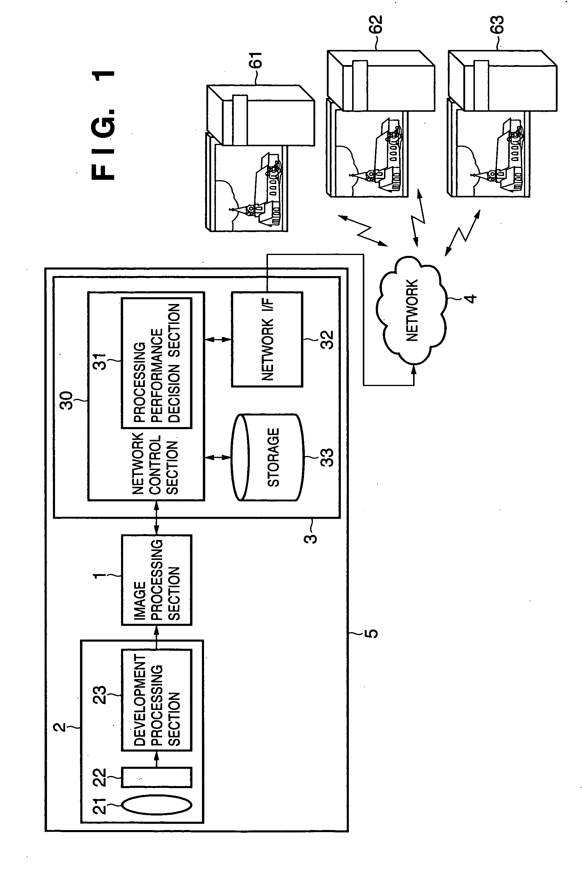
[0037]FIG. 1 is a block diagram showing the structure of an image sensing apparatus according to a First Embodiment. In FIG. 1, an image sensing apparatus 5 is roughly divided into three components; an image processing section 1, an image sensing section 2 and a communication section 3. The image sensing section 2 includes a lens 21 to which image is input, a photoelectric conversion sensor (hereinafter referred to as “sensor”) 22 which converts the light condensed by the lens 21 to an electric signal and a development processing section 23 which develops the signal obtained from the sensor 22. The development processing section 23 carries out luminance / color signal separation processing, noise reduction processing, reference γ correction processing and color correction / color signal suppression processing on the data (data of each of RGB elements in the case of a primary color filter) output from the sensor 22. Final output data of the image data output from the development processi...

second embodiment

[0074] The First Embodiment has explained the processing in the case where the same image is subjected to different image corrections for three connection destinations simultaneously. Furthermore, the First Embodiment has explained the processing of applying one type of image processing to the respective output destinations and outputting the processing results, but it may be necessary to apply a plurality of types of image processing depending on the request from the display apparatus at the output destination. Example of this are luminance correction+filter processing, luminance correction+extraction at a desired angle of view, etc. The Second Embodiment will explain a structure for realizing such composite processing.

[0075] As in the case of the First Embodiment, an image sensing apparatus 5 and a plurality of display apparatuses are connected through a network (FIG. 1). FIG. 6 illustrates operations of various processing sections of an image processing section 1 according to th...

third embodiment

[0088] In the First Embodiment and Second Embodiment, the image processing section 1 has the inner structure as shown in FIG. 4 in which the respective image correction processes are arranged in parallel so as to distribute image data to correction processing specified by the demultiplexer section. However, when such a structure is adopted, the data flow control by the control sequencer section 400 becomes complicated and the processing time possibly increases.

[0089] In order to solve the above described problem, a Third Embodiment will describe an example in which the image correction execution section 413 is modified. As shown in FIG. 8, according to the Third Embodiment, the respective processing sections in an image correction execution section 1001 are connected in series like a pipeline. A flag processing section 1010 for adding a flag indicating whether each correction process should be carried out or not and a parameter indicating an amount of each of various types of corre...


PUM


Abstract

A data processing apparatus includes a plurality of image processing units which execute different processes on input image data and an encoding unit which encodes the image data. A generation unit selects an image processing unit to be used from among a plurality of image processing units based on requests from a plurality of output destinations to process image data of each frame input. The selected image processing unit processes the image data in time-series and the encoding unit encodes the processed image data. Thus, a plurality of image data corresponding to requests from a plurality of output destinations are generated.

Description

FIELD OF THE INVENTION [0001] The present invention relates to video data processing, and more particularly, to a data processing apparatus and a control method thereof preferably applicable to image transmission over a network. BACKGROUND OF THE INVENTION [0002] With the widespread use of the Internet, information is commonly transmitted via WWW (World Wide Web), etc., in recent years. Under such a circumstance, an image sensing apparatus has emerged which has functions of taking images in real time and delivering the images over a network. [0003] On the other hand, when a camera image delivery service is provided for a user over a network, there is a proposal on a delivery of image data suitable for an environment on the user side. [0004] Japanese Patent Laid-Open No. 2001-197458 describes an image processing apparatus in which information (amount of γ correction) specific to a display (CRT, LCD, etc., as a PC monitor) for an image display on the user side is transmitted to a came...

Claims


Application Information

Patent Timeline
Patent Type & Authority Applications(United States)
IPC IPC(8): G06K9/36G06F13/00H04N7/173H04N21/2662
CPCH04N21/234336H04N21/23439H04N21/6377H04N21/4621H04N21/4728H04N21/2662
Inventor ENDO, YOSHIYUKI
Owner CANON KK
Why Eureka
Try Eureka