Medical kinematic analysis apparatus and a medical kinematic analysis method
a medical kinematic analysis and apparatus technology, applied in the field of medical kinematic analysis methods, can solve the problems that the conventional medical kinematic analysis apparatus cannot measure or analyze the motion due to twist or rotation along with the motion
- Summary
- Abstract
- Description
- Claims
- Application Information
AI Technical Summary
Benefits of technology
Problems solved by technology
Method used
Image
Examples
first embodiment
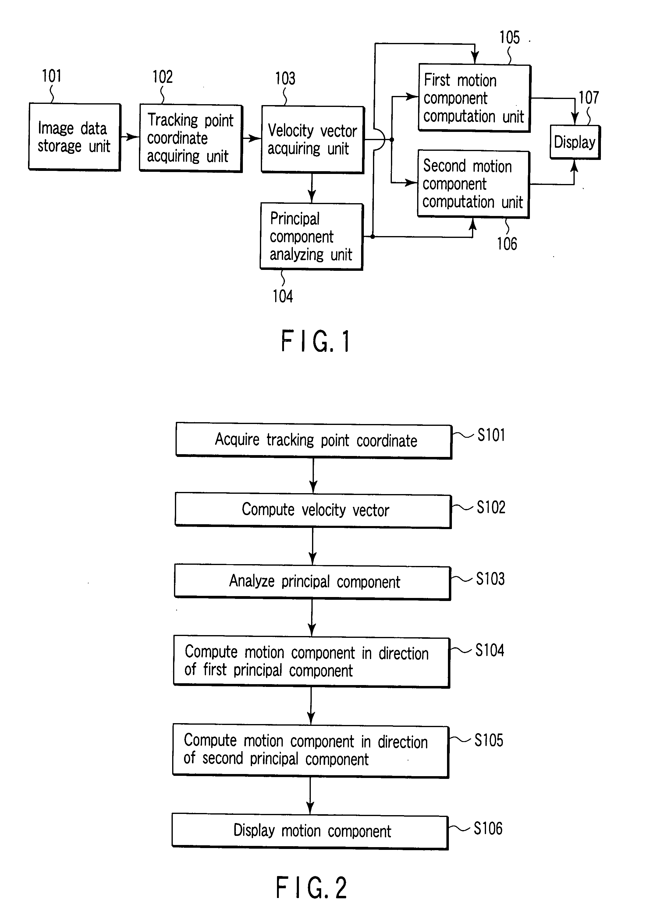
[0026]FIG. 1 is a block diagram of a medical kinematic analysis apparatus concerning the first embodiment of the present invention.
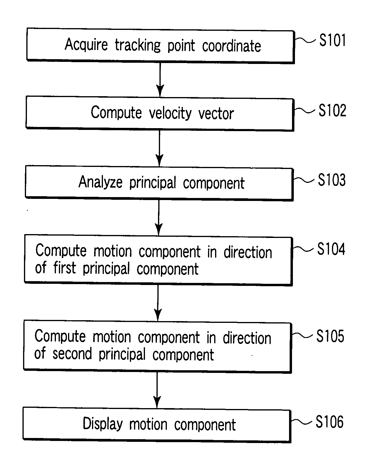
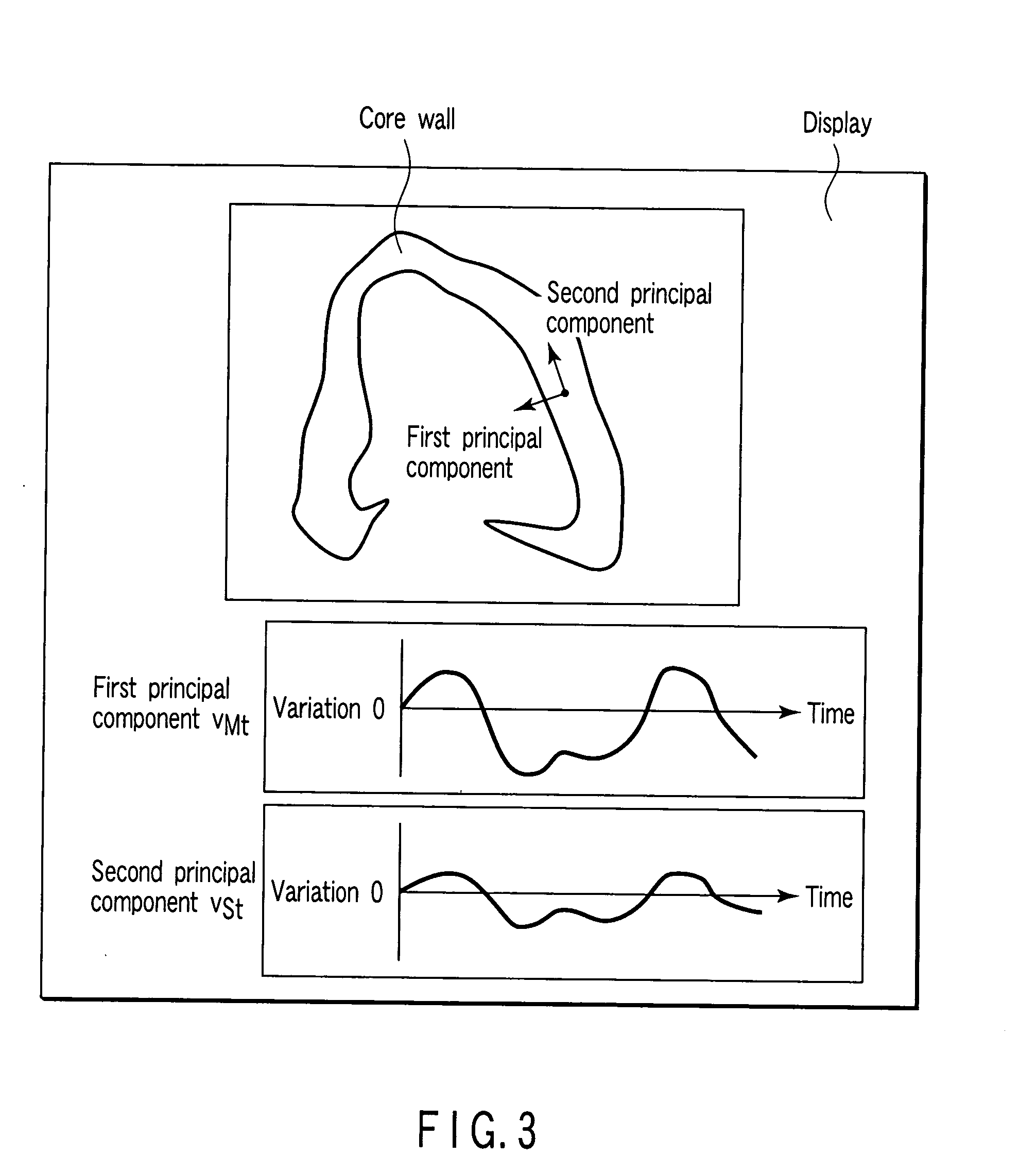
[0027] According to the medical kinematic analysis apparatus concerning the first embodiment, an image data storage unit 101 is configured to store time-series image data obtained by capturing a heart as a subject. A tracking point coordinate acquiring unit 102 is configured to acquire coordinate time series data representing a coordinate of the tracking point on the heart from the time-series image data stored in the image data storage unit 101. A velocity vector acquiring unit 103 is configured to acquire time-series data of a velocity vector of the tracking point as time-series motion information from the coordinate time-series data which is acquired with the tracking point coordinate acquiring unit 102. A principal component analyzing unit 104 is configured to subject the time-series motion information acquired with the velocity vector acquiring uni...
second embodiment
[0075] In the first embodiment, the time series data of the velocity vector of the tracking point is subjected to principal component analysis to obtain first and second component directions, and the first component direction is assumed to be a cardiac systole / diastolic direction and the second component direction is assumed to be a motion directions such as a cardiac twist or rotation.
[0076] In the second embodiment, at first, a cardiac contour is extracted. The normal direction of the contour is assumed to be a motion direction of a cardiac systole / diastolic, and the tangential direction of the contour is assumed to be a motion direction such as cardiac twist or rotation. There will be explained a method of acquiring the motion component of the tracking point in these directions.
[0077]FIG. 6 is a block diagram of a medical kinematic analysis apparatus concerning the second embodiment of the present invention.
[0078] According to the medical kinematic analysis apparatus concernin...
third embodiment
[0098] In the first embodiment, the time series data of the velocity vector of the tracking point is subjected to principal component analysis, and the first component direction is set to be the cardiac systole / diastolic direction. Further, in the second embodiment, the cardiac contour is extracted, and the normal direction of the contour is set to be the cardiac systole / diastolic.
[0099] In the third embodiment, there will be explained a method of computing a motion component of a systole / diastolic direction and a motion component of a direction such as twist or rotation based on a manually set cardiac systole / diastolic direction. FIG. 11 is a block diagram of a medical kinematic analysis apparatus concerning the third embodiment of the present invention.
[0100] According to the medical kinematic analysis apparatus concerning the third embodiment, an image data storage unit 301 is configured to store time-series mage data obtained by capturing a heart as a subject. A tracking point...
PUM
 Abstract
Description
Claims
Application Information
 - R&D
- Intellectual Property
- Life Sciences
- Materials
- Tech Scout
- Unparalleled Data Quality
- Higher Quality Content
- 60% Fewer Hallucinations
Browse by: Latest US Patents, China's latest patents, Technical Efficacy Thesaurus, Application Domain, Technology Topic, Popular Technical Reports.
© 2025 PatSnap. All rights reserved.Legal|Privacy policy|Modern Slavery Act Transparency Statement|Sitemap|About US| Contact US: help@patsnap.com


