Method and apparatus for anterior and posterior mobilization of the human ankle

a human ankle and anterior and posterior technology, applied in the field of human ankle anterior and posterior mobilization, can solve the problems of difficult to quantify the force of manual mobilization, difficulty in transporting, and difficulty in transferring accessories, etc., and achieve the effects of easy transportation, reduced pain of patients from injury/surgery, and increased range of motion and strength

Inactive Publication Date: 2006-03-16
NUSHART MICHAEL J
View PDF13 Cites 7 Cited by
  • Summary
  • Abstract
  • Description
  • Claims
  • Application Information

AI Technical Summary

Benefits of technology

[0043] The invention has the advantage that the unit is lightweight and small enough to be transported easily allowing patients to use it at home between physical therapy sessions at a physical therapy clinic.
[0044] The invention has the advantage that the method and apparatus provides an array of straps which allow the joint mobilization to begin with light straps early in the physical therapy rehabilitation process with progress to heavier straps as determined by the physical therapy practitioner. Shortly after injury the mobilization begins with light straps with the tensile value of straps increased as patient's pain from the injury / surgery decreases and range of motion and strength is gained.
[0045] The invention has the advantage that an adjustment feature of a hook anchor allows the height to be changed. As the distance between the hook anchor, and a force lever pivot point (cross pin) change, so does angle of pull. This allows the physical therapy practitioner to precisely achieve the direction and amount of glide desired. Also, the ratio of travel changes when comparing the distance traveled at the top of the lever to the distance traveled at the hook anchor point. This allows the physical therapy practitioner to tailor the force applied to the ankle joint based on the individual patient's progress.
[0046] The invention has the advantage that graduated indicator marks on the force lever, a measuring tape affixed to the baseplate alongside each anchor track and footplate elevation device markings that indicate the elevation angle, all allow repeatability of settings.
[0047] The invention has the advantage that the foot strap is secured to the footplate by two pivoting strap anchors and this pivoting action enables achievement of the appropriate angle between the plane of the footplate and the plane of the strap. This allows precise placement of the strap at the head of the talus.
[0048] The invention has the advantage that since the two parts of a stirrup strap are attached to a heel cup strap with hook and loop material as well as connected to each other with hook and loop, a wide range of adjustability is achieved. The stirrup strap ensures that the heel cup strap doesn't ‘ride up’ above the patient's heel and impinge on the Achilles tendon.

Problems solved by technology

Existing treatment involves manual mobilization techniques, which, although generally effective, lack replicability from one patient to the next and, from one physical therapy practitioner to the next The force of manual mobilization also is difficult to quantify.
These accessory motions of glide are frequently impaired as a result of an ankle injury resulting in dysfunction of movement.
This practice, although generally effective, is subject to inconsistent results due to essential variables in its application.
Typically, passive manual mobilization techniques do not allow active movement of the joint, particularly dorsiflexion that is beneficial during mobilization
Certain more aggressive mobilization techniques run the risk of shock loading the patient's ankle joint, i.e. applying the force too quickly and / or forcefully.
The slightest delay in communicating pain can result in undesired results such as increased and prolonged pain and delayed recuperation.
During early stages of rehabilitation, patients can experience frequent intense pain.
Unfortunately physical therapy appointments are not daily events resulting in the patient having to endure pain on days without appointments.
It is not possible to perform manual mobilization of the ankle joint on oneself.

Method used


Image

  • Method and apparatus for anterior and posterior mobilization of the human ankle
  • Method and apparatus for anterior and posterior mobilization of the human ankle
  • Method and apparatus for anterior and posterior mobilization of the human ankle

Examples


Embodiment Construction

[0050] A more complete understanding of the invention may be obtained by reference to the drawings, in which:

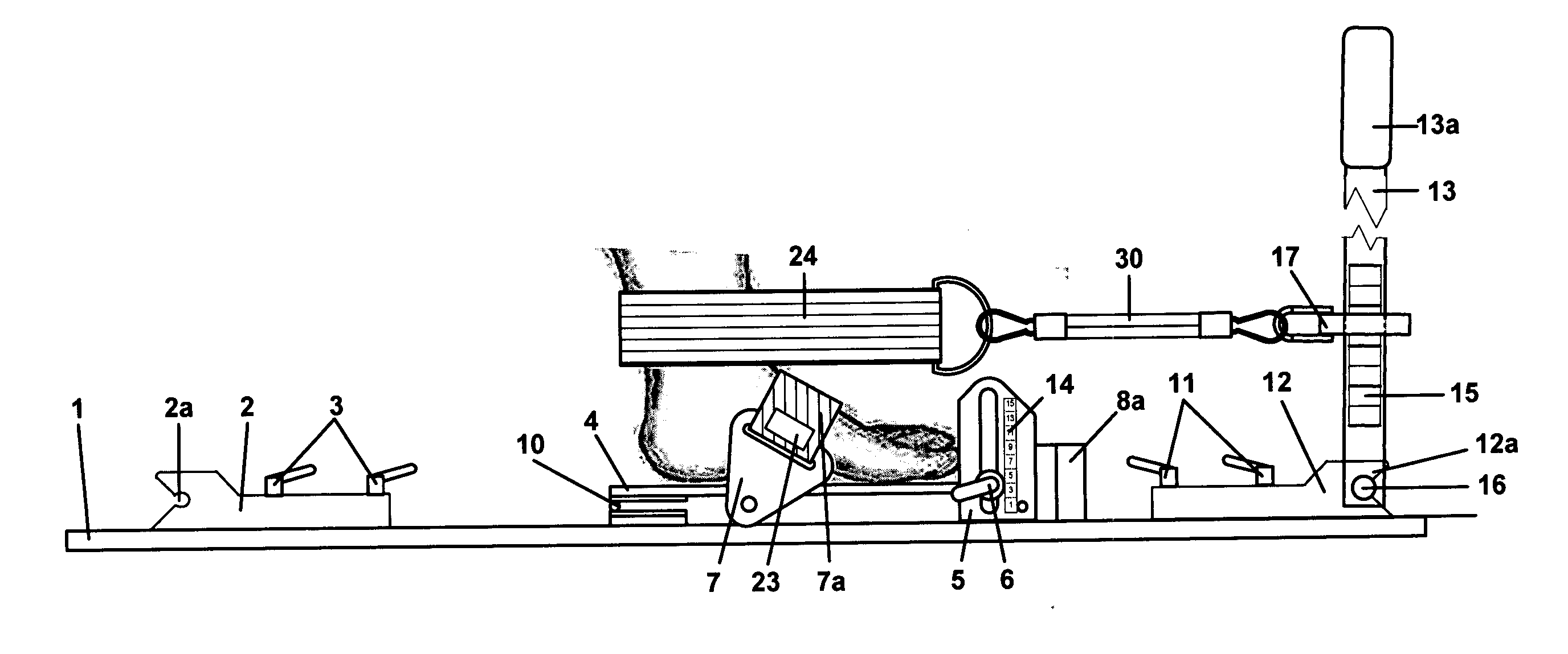
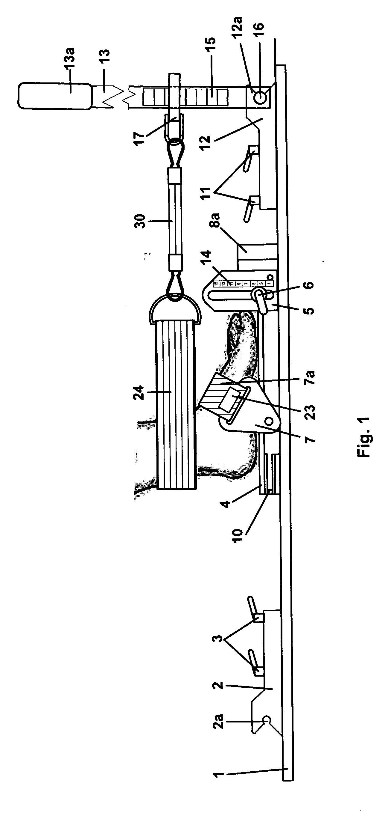
[0051]FIG. 1 is an elevation view of the present invention in the anterior mobilization configuration, with the Ankle Mortise Strap, force strap and, force lever installed;

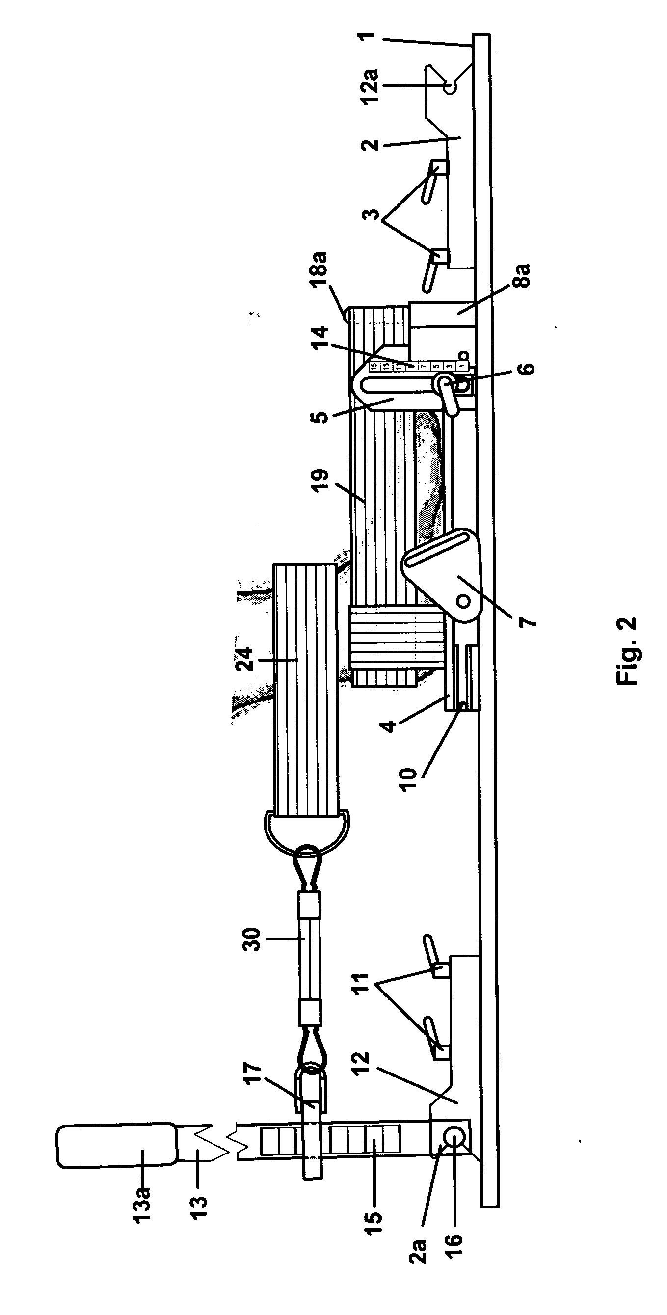
[0052]FIG. 2 is an elevation view of the apparatus of FIG. 1 in the posterior mobilization configuration, with heel cup, Ankle Mortise Strap, force strap and, force lever installed;

[0053]FIG. 3 is an elevation view of the apparatus of FIG. 1 with the footplate in the horizontal position;

[0054]FIG. 4 is an elevation view of the apparatus of FIG. 1 with the footplate elevated to a maximum angle;

[0055]FIG. 5 is a plan view of the apparatus shown in FIG. 1;

[0056]FIG. 6 is a view of the force lever with hook anchor point of the apparatus shown in FIG. 1;

[0057]FIG. 7 is a view of the inside of the heel cup strap with anchor pins installed and stirrup strap halves disconnected;

[0058]FIG. 8 is a view of the...


PUM


Abstract

An apparatus for anterior and posterior mobilization of the human talocrural joints for rehabilitation and/or therapeutic utilization. A patient's foot is secured in an apparatus and an Ankle Mortise Strap is looped around the mortise of an ankle of the foot A force strap is attached to the ends of the Ankle Mortise Strap. Anterior mobilization is achieved by moving the force strap ventrally from the foot so that the foot including the talus remains stationary while the tibia and fibula glide anteriorly. Posterior mobilizations are achieved by securing the foot, and looping an Ankle Mortise Strap around the front of the ankle. A force strap is attached to the ends of the Ankle Mortise Strap. Posterior mobilization is achieved by moving the force strap dorsally from the foot so that the foot including the talus remains stationary while the tibia and fibula glide posteriorly.

Description

[0001] I hereby claim the benefit under 35 U. S. C. Section 119(e) of United States Provisional application 60 / 610,479 filed Sep. 15, 2004. BACKGROUND OF THE INVENTION [0002] 1. Field of the Invention [0003] The invention relates generally to the field of physical therapy methods and apparatus to prepare an injured ankle joint for the strengthening process inherent in physical medicine and rehabilitation by reducing pain and stiffness, while increasing flexibility and range of motion. [0004] 2. Description of the Prior Art [0005] U.S. Pat. No. 4,306,714 to Loomis, et al. filed Dec. 22, 1981 “Iso-energetic Ankle Exerciser” discloses an exercise device for the hands or feet in which the user supplies the force and motion by one hand or foot which will be countered by a resistance and similar motion of the other hand or foot. [0006] This instrument rotates in three axes and is capable of being restrained from movement in each axis independently. The possible movement is therefore about...

Claims


Application Information

Patent Timeline
Patent Type & Authority Applications(United States)
IPC IPC(8): A61F5/00
CPCA61H1/0266A61H2201/1642Y10S482/907
Inventor NUSHART, MICHAEL J.
Owner NUSHART MICHAEL J
Why Eureka
Try Eureka