Pumping unit with variable work stroke and return stroke torque factor characteristics

a technology of torque factor and pumping unit, which is applied in the direction of piston pump, positive displacement liquid engine, gearing, etc., can solve the problems of insufficient formation pressure and typical type of pumping unit that requires substantial counterbalancing, so as to reduce reduce the overall structure of the pumping unit. , the effect of significantly reducing the amount of counterbalance weigh

Inactive Publication Date: 2006-03-23
JENSEN INT
View PDF15 Cites 17 Cited by
  • Summary
  • Abstract
  • Description
  • Claims
  • Application Information

AI Technical Summary

Benefits of technology

[0022] The ability to selectably vary these characteristics occurring in the pumping cycle enables a manufacturer to design a pumping unit in which stress on the pumping unit for a given depth well is significantly reduced compared to a standard pumping unit on the market today. Further, counterbalancing is always required of the walking beam. The typical counterbalance includes weights placed on the walking beam at the end thereof that is opposite the horsehead to offset the weight of the sucker rod string plus the weight of a column of a fluid as it is being lifted during the pump stroke. By supporting the gear reducer on the walking beam the amount of counterbalance weight is significantly reduced. In addition, by being able to selectably adjust the pumping unit characteristics the peak stress loads typically encountered are significantly minimized thereby permitting the overall structure of the pumping unit be significantly reduced.

Problems solved by technology

In other parts of the world formation pressures are insufficient to force the crude oil to the earth's surface and therefor the crude oil must be pumped.
This typical type of pumping unit requires substantial counterbalancing.

Method used


Image

  • Pumping unit with variable work stroke and return stroke torque factor characteristics
  • Pumping unit with variable work stroke and return stroke torque factor characteristics
  • Pumping unit with variable work stroke and return stroke torque factor characteristics

Examples


Embodiment Construction

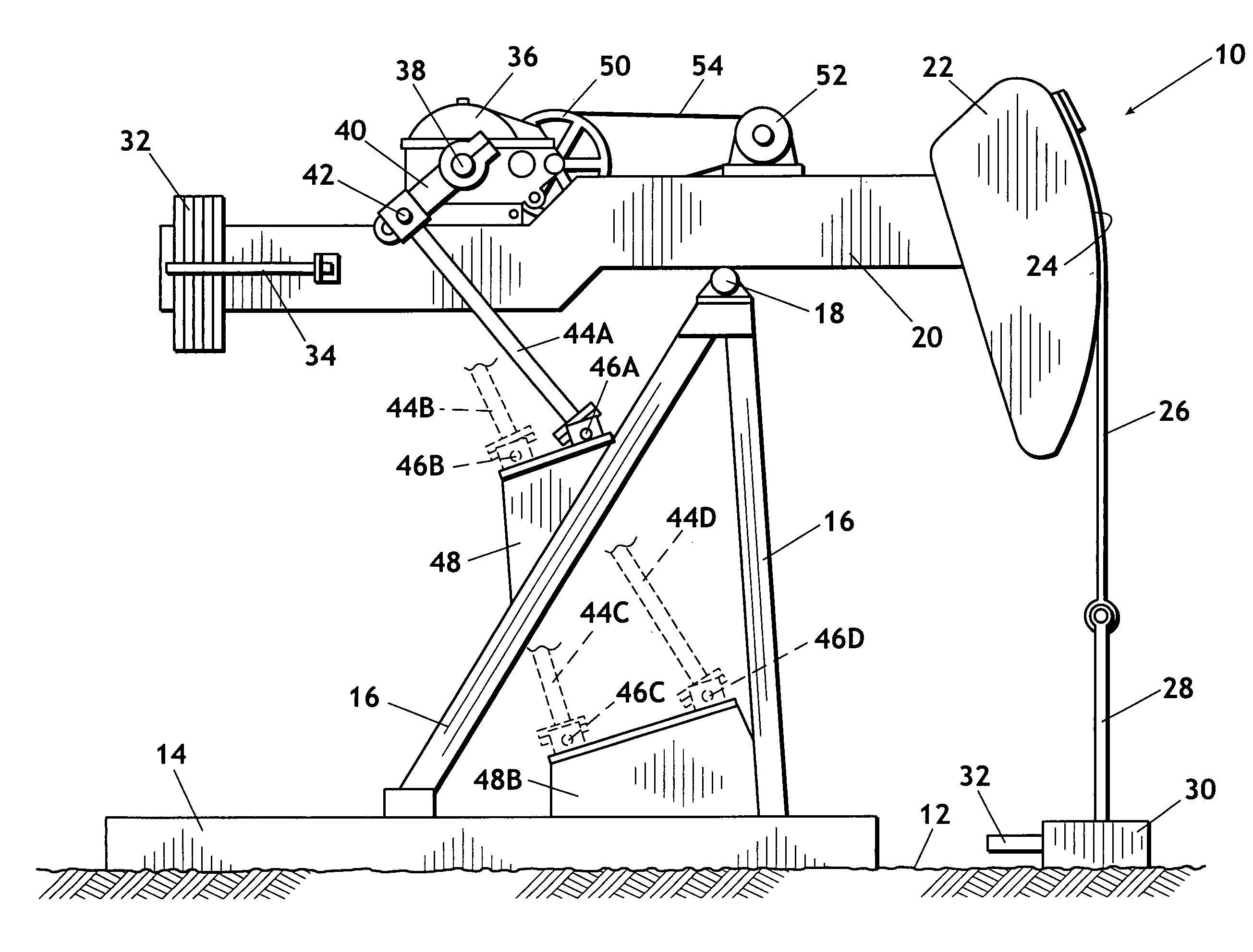
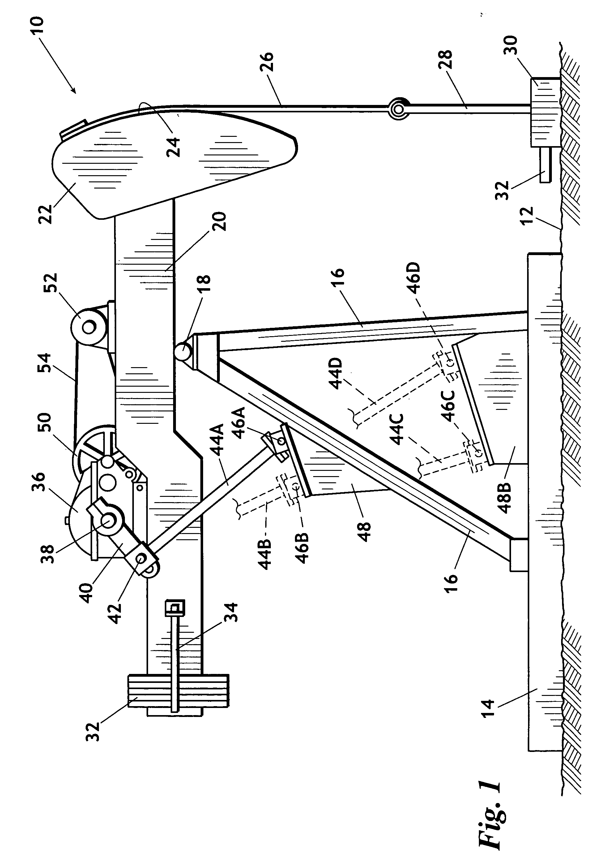
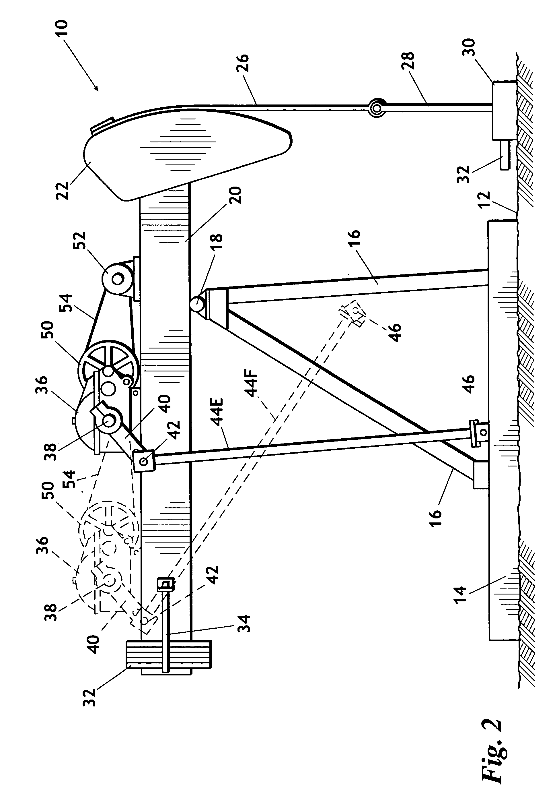
Elements shown by the drawings are identified by the following numbers:10pumping unit12earth's surface14base16sampson post structure18pivot bearing20walking beam22horsehead24forward face26sucker rod sling28sucker rod string30well head32production pipe32counterweight34positioning mechanism36gear reducer38drive shaft40A-D crank arm42crank pin bearing44pitman rod46A-Dpivot bearing48A-Bpitman rod support structure50drive wheel52electric motor54belts56standard torque curve58torque curve this invention60RMS level standard unit62RMS level - this invention64average torque - standard unit66average torque - this invention

[0031] Referring to FIG. 1, a pumping unit representing this invention is generally indicated by the numeral 10, the pumping unit being shown supported on the earth's surface 12. A base 14 that rests on the earth's surface 12 supports an upwardly extending sampson post structure 16 that is typically formed of steel angular components as illustrated. Affixed to the upper end o...


PUM


Abstract

A pumping unit system having vertical sampson post, a walking beam pivotally supported at the upper end of the sampson post and a horsehead affixed at a forward end thereof that supports a reciprocated sucker rod string, including a gear reducer mounted at selectable positions on the walking beam and having a horizontally extending drive shaft, a crank arm affixed to the drive shaft the spacing between a selectable length pitman rod having a first end secured to said crank arm and a second end having a pitman bearing that is selectably mountable to a plurality of pitman bearing locations and a prime mover connected to the gear reducer and wherein the characteristics of the pumping unit are determined by the selectable position of the gear reducer, the selectable length of the crank arm, the selectable length of the pitman rod, and the selectable pitman bearing location.

Description

REFERENCE TO PENDING APPLICATIONS [0001] This application is not based upon any pending domestic or international patent applications. REFERENCE TO MICROFICHE APPENDIX [0002] This application is not referenced in any microfiche appendix. BACKGROUND OF THE INVENTION [0003] 1. Field of the Invention [0004] The present invention relates to a pumping unit for actuating a down hole pump for pumping fluid, primarily crude oil, from subterranean oil-bearing formations to the earth's surface. More particularly, the present invention relates to a pumping system that includes a sampson post extending upwardly from a base supported on the earth's surface, a walking beam pivotally supported by a saddle bearing at the sampson post upper end with a horsehead affixed at a forward end of the walking beam to receive the upper end of a downwardly extending sucker rod string by which a subsurface pump is vertically reciprocated, the system including a gear reducer mounted on the walking beam for rotat...

Claims


Application Information

Patent Timeline
Patent Type & Authority Applications(United States)
IPC IPC(8): F16H21/32
CPCF04B47/022Y10T74/18182Y10T74/18936
Inventor JENSEN, JAMES B.
Owner JENSEN INT
Why Eureka
Try Eureka