Control of vehicle generator using PWM signal with specially determined duty and frequency

a technology of vehicle generators and control apparatuses, applied in the direction of electric generator control, dynamo-electric converter control, generation protection through control, etc., can solve the problems of low electric potential of signal lines, inability of external control apparatuses to distinguish the fault condition of generators from the fault condition of signal lines, and the inability of the apparatus to inform the external control apparatus. , to achieve the effect of high stability

Inactive Publication Date: 2006-03-23
DENSO CORP
View PDF9 Cites 24 Cited by
  • Summary
  • Abstract
  • Description
  • Claims
  • Application Information

AI Technical Summary

Benefits of technology

[0014] It is, therefore, the first object of the present invention to provide a control apparatus for a vehicle generator (or alternator), which can inform an external control apparatus of a duty of a switch for controlling a field current supply to the generator and fault conditions of the generator using a single signal and enable the external control apparatus to distinguish fault conditions of the generator from those of a signal line connecting the two control

Problems solved by technology

However, the above control apparatus cannot concurrently inform the external control apparatus of the duty of the transistor and the fault condition of the generator with a single signal, since the second signal is configured to have a low level.
Further, the electric potential of the signal line will drop to a low level when the signal line is short-circuited to the ground.
Thus, it is impossible for the external control apparatus to distinguish the fault condition of the generator from that of the signal line.
As a result, the relationship between the reception time of the PWM signal and transmission time of the PWM command signal for the external control apparatus will also vary with time, thus causing instability of the whole

Method used


Image

  • Control of vehicle generator using PWM signal with specially determined duty and frequency
  • Control of vehicle generator using PWM signal with specially determined duty and frequency
  • Control of vehicle generator using PWM signal with specially determined duty and frequency

Examples


Embodiment Construction

[0048] The preferred embodiment of the present invention will be described hereinafter with reference to FIGS. 1-5.

[0049] It should be noted that, for the sake of clarity and understanding, identical components having identical functions in each of the figures have been marked with the same reference numerals.

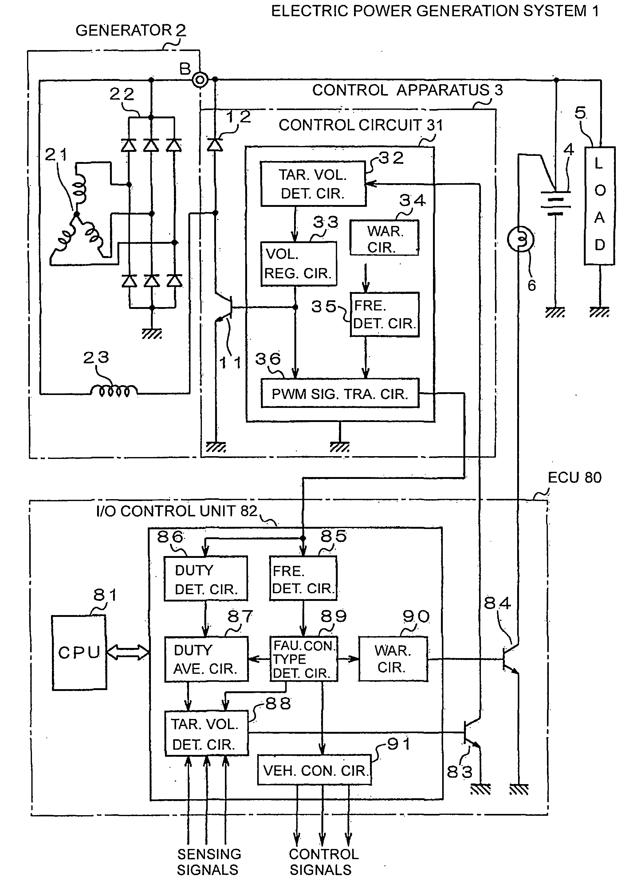
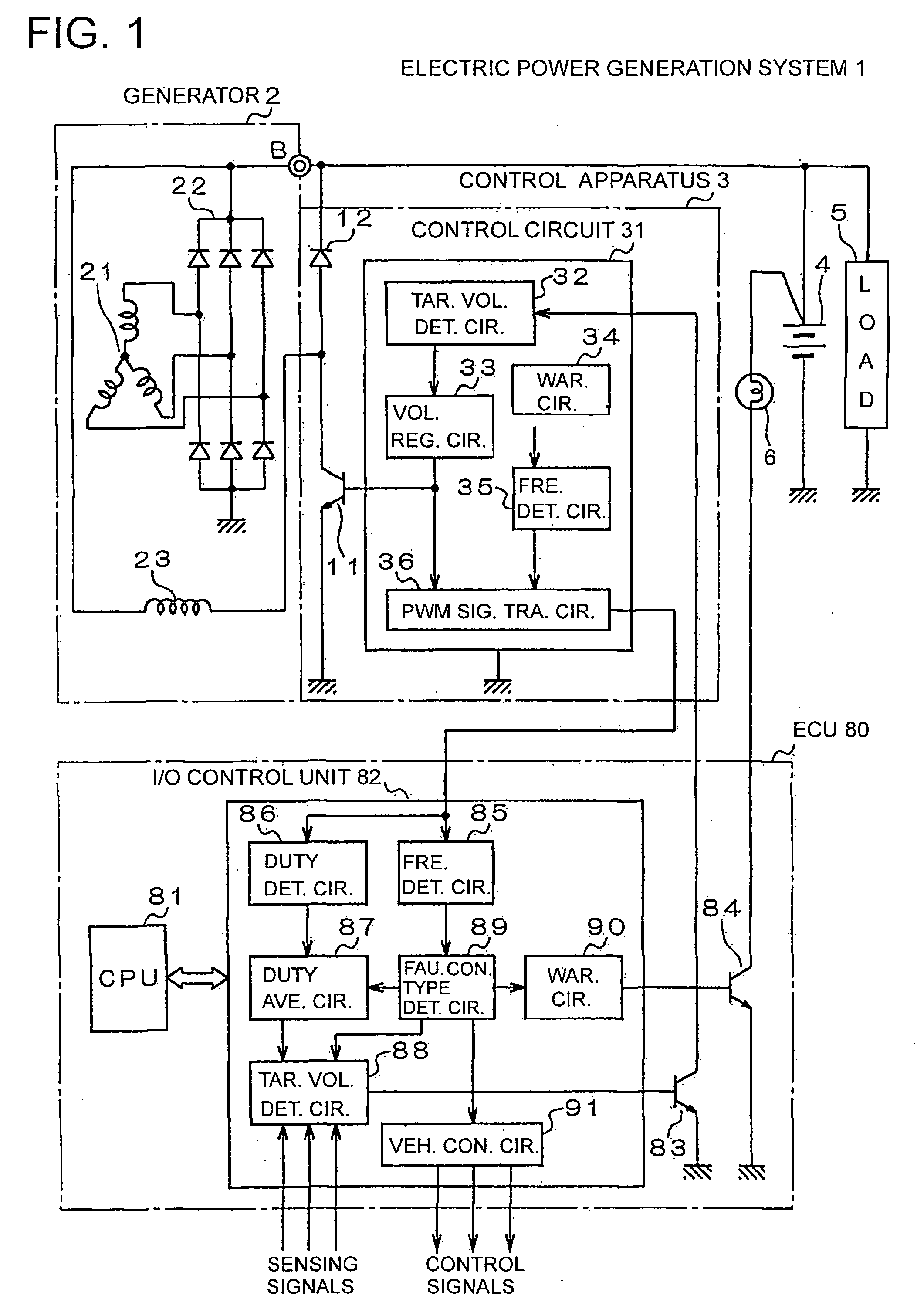
[0050]FIG. 1 shows the overall configuration of an electric power generation system 1 according to an embodiment of the present invention. The electric power generation system 1 is for use in a motor vehicle.

[0051] As shown in FIG. 1, the electric power generation system 1 includes a generator (or alternator) 2, a control apparatus 3, and an ECU (Electrical Control Unit) 80.

[0052] The generator 2 includes a three-phase stator winding 21, a rectification circuit 22, and a field winding 23. The stator winding 21 and filed winding 23 are respectively provided on a stator and a rotor of the generator 2. The rectification circuit 22 is configured to full-wave rectify the three-p...


PUM


Abstract

A control apparatus for a vehicle generator includes a switch, a regulator, a fault condition detector, and a PWM signal generator. The switch is selectively turned on and off so as to intermittently excite the generator. The regulator controls on/off operation of the switch so as to bring an output of the generator into agreement with a target value. The fault condition detector detects a fault condition of the generator. The PWM signal generator generates and outputs a PWM signal that has a duty determined as a function of a duty of the on/off operation of the switch and a frequency determined based on if the fault condition of the generator is detected by the fault condition detector. Consequently, the control apparatus can inform an external control apparatus of the duty of the on/off operation of the switch and the fault condition of the generator with the single PWM signal.

Description

CROSS-REFERENCE TO RELATED APPLICATION [0001] This application claims priority from Japanese Patent Application No. 2004-268195, filed on Sep. 15, 2004, the content of which is hereby incorporated by reference into this application. BACKGROUND OF THE INVENTION [0002] 1 Technical Field of the Invention [0003] The present invention relates generally to generators and electric power generation systems for motor vehicles. More particularly, the invention relates to a control apparatus for a vehicle generator, which provides information about operation of the generator to an external control apparatus using a PWM (Pulse Width Modulated) signal that has a duty and a frequency both of which are specially determined. [0004] 2 Description of the Related Art [0005] Several methods have been proposed to provide an external control apparatus with information about operation of a vehicle generator, such as fault conditions of the generator. [0006] For example, Japanese Patent First Publication N...

Claims


Application Information

Patent Timeline
IPC IPC(8): H02H7/06H02P11/00H02P9/00
CPCH02J7/1461Y02T10/92H02P9/006H02J7/245H02J7/2434H02J7/0047
Inventor INOKUCHI, TAKATOSHIASADA, TADATOSHI
Owner DENSO CORP
Why Eureka
Try Eureka