Inverted magnetic isolator

a magnetic isolator and inverter technology, applied in the direction of recording information storage, measurement using dc-ac conversion, instruments, etc., can solve the problems of insufficient devices for sensing magnetic fields, lack of satisfactory remedial or supplementary measures in such arrangements to improve the limited sensitivity of hall effect devices

Active Publication Date: 2006-03-23
NVE CORP
View PDF33 Cites 43 Cited by
  • Summary
  • Abstract
  • Description
  • Claims
  • Application Information

AI Technical Summary

Problems solved by technology

While this has long been done for magnetic fields generated by substantial currents, such sensing becomes more difficult to accomplish in smaller ranges of currents that include relatively quite small currents.
Such devices are often not satisfactory for sensing the magnetic fields due to small currents because of the limited sensitivity they exhibit with respect to magnetic fields.
Furthermore, there is often a lack of satisfactory remedial or supplementary measures in such arrangements for improving the limited sensitivity of Hall effect devices.
The use of field concentrators is

Method used


Image

  • Inverted magnetic isolator
  • Inverted magnetic isolator
  • Inverted magnetic isolator

Examples


Embodiment Construction

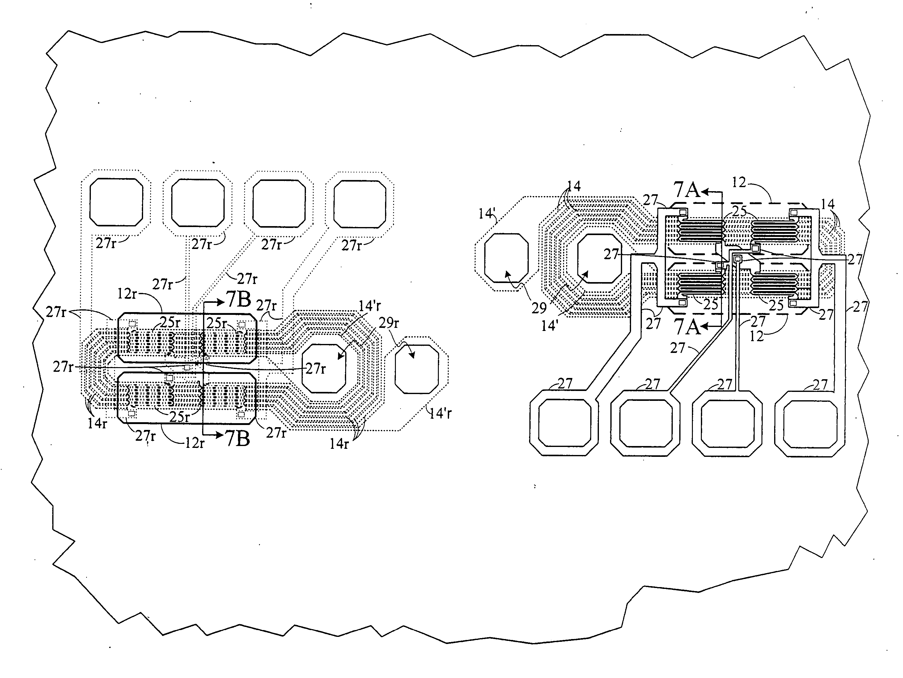
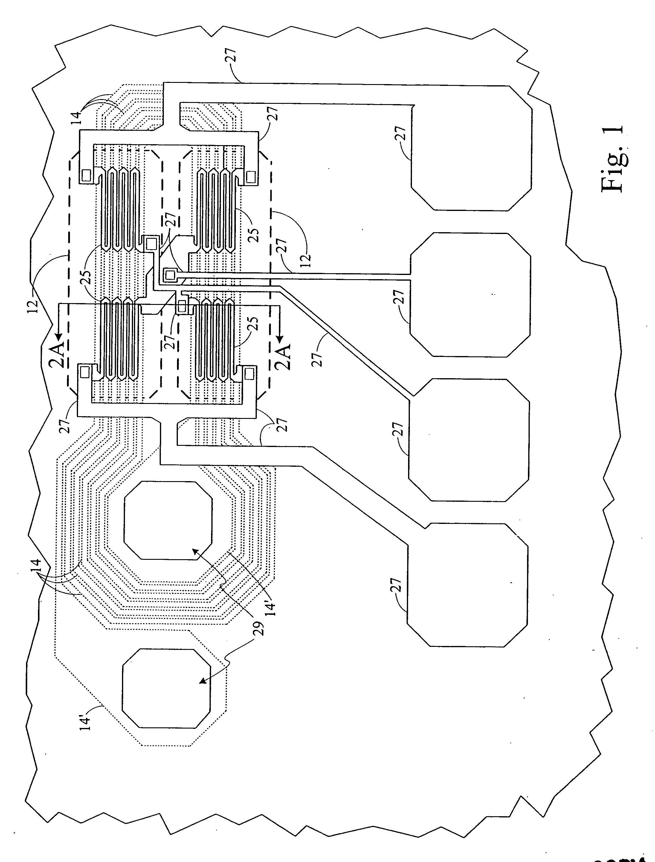
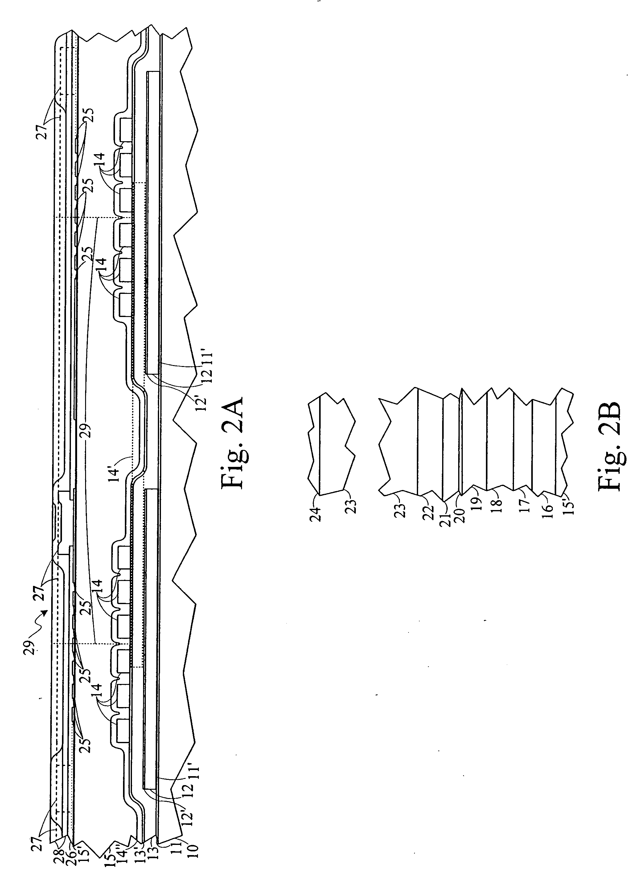
[0026] A basic “sandwich” structure magnetic field sensor has a sensor electrical resistance versus applied external field characteristic for an external magnetic field applied in one direction perpendicular to its easy axis that generally appears in its graph on a resistance versus field Cartesian coordinates graph as a horizontal line at the sensor minimum resistance value except for an excursion therein to greater resistance values located at or near to the zero applied magnetic field value. This excursion typically appears as a more or less “baseless” isosceles triangular shape with an increase from the minimum sensor resistance value to a peak sensor resistance value at zero field followed by a decrease to the minimum sensor resistance value, or it may appear to be a triangular shaped excursion to higher resistance values except for a flat, or “plateau”, portion at the top thereof at the maximum sensor resistance value. Thus, plotting the characteristics resulting from applying...


PUM


Abstract

A current determiner comprising a first input conductor and a first current sensor, formed of a plurality of magnetoresistive, anisotropic, ferromagnetic thin-film layers at least two of which are separated from one another by a nonmagnetic layer positioned therebetween, and both supported on a substrate adjacent to and spaced apart from one another so they are electrically isolated with the first current sensor positioned in those magnetic fields arising from any input currents. A first shield/concentrator of a material exhibiting a substantial magnetic permeability is positioned between the substrate and the first input conductor. The substrate can include a monolithic integrated circuit structure containing electronic circuit components of which at least one is electrically connected to the first input conductor. A similar second current sensor can be individually formed, but can also be in the current determiner structure that is supported on the substrate along with a second input conductor supported on the substrate suited for conducting input currents therethrough. This second input conductor is positioned at that side of the second current sensor opposite to that side thereof facing the substrate so as to be adjacent to, yet spaced apart from, the second current sensor to thereby be electrically isolated from any direct circuit interconnection therewith on the substrate but to have the second current sensor positioned in those magnetic fields arising from the input currents in the second input conductor. In addition, a second shield/concentrator layer of material exhibiting a substantial magnetic permeability to serve as a magnetic field concentrator is positioned at that side of the second input conductor opposite to that side thereof facing the substrate. In the first instance, the second shield/concentrator layer is electrically connected to the second input conductor, and can be so connected in the second instance.

Description

CROSS-REFERENCE TO RELATED APPLICATION [0001] This application claims the benefit of Provisional Application No. 60 / 610,700 filed on Sep. 17, 2004 for “INVERTED MAGNETIC ISOLATOR”.BACKGROUND OF THE INVENTION [0002] The present invention relates to ferromagnetic thin-film structures exhibiting relatively large magnetoresistive characteristics and, more particularly, to such structures used to magnetically couple signals from a source to an isolated receiver. [0003] Many kinds of electronic systems make use of magnetic devices including both digital systems, such as memories, and analog systems such as field sensors. Magnetometers and other magnetic sensing devices are used extensively in many kinds of systems including magnetic disk memories and magnetic tape storage systems of various kinds. Such devices provide output signals representing the magnetic field sensed thereby in a variety of situations. [0004] One use for such magnetic field sensors is the sensing of magnetic fields ge...

Claims


Application Information

Patent Timeline
IPC IPC(8): G01R15/18
CPCG01R15/205G01R15/202G01R15/207H01L2924/0002H01L2924/00
Inventor MYERS, JOHN K.DAUGHTON, JAMES M.
Owner NVE CORP
Why Eureka
Try Eureka