Isolation of hosts connected to an access network

Inactive Publication Date: 2006-03-23
TELEFON AB LM ERICSSON (PUBL)
View PDF11 Cites 222 Cited by
  • Summary
  • Abstract
  • Description
  • Claims
  • Application Information

AI Technical Summary

Benefits of technology

[0046] Hereby a method and an arrangement are achieved where all the traffic is forced via the access router and hosts connected to the access network are not able to communicate directly with each other. Furthermore only one VLAN is used for the downlink traffic from the access router and therefore broadcasting of traffic from the access router is performed effectively. Moreover, since the hosts belong to the same IP subnet, IP addresses are saved, because the access router only needs one IP address ass

Problems solved by technology

IP addresses are a scarce resource and consequently it is a disadvantage that a large number of IP addresses have to be allocated to the access router.
In addition, the administrative work involved in configuring all these IP addresses and subnet masks may be substantial.
Yet a disadvantage is that it is not possible to reach all hosts simultaneously with a single broadcast message.
Although the IP address configuration is greatly simplified by the VLAN aggregation concept, the broadcast limitations still remain.
This consumes processing resources as well as bandwidth in the access router.
These have the limitation that a switch in which sub-VLANs and a super-VLAN are defined also has to be the super-VLAN router (which is unfortunate).
It is unclear whether this limitation is inherent in the concept o

Method used


Image

  • Isolation of hosts connected to an access network
  • Isolation of hosts connected to an access network
  • Isolation of hosts connected to an access network

Examples


first embodiment

LANS

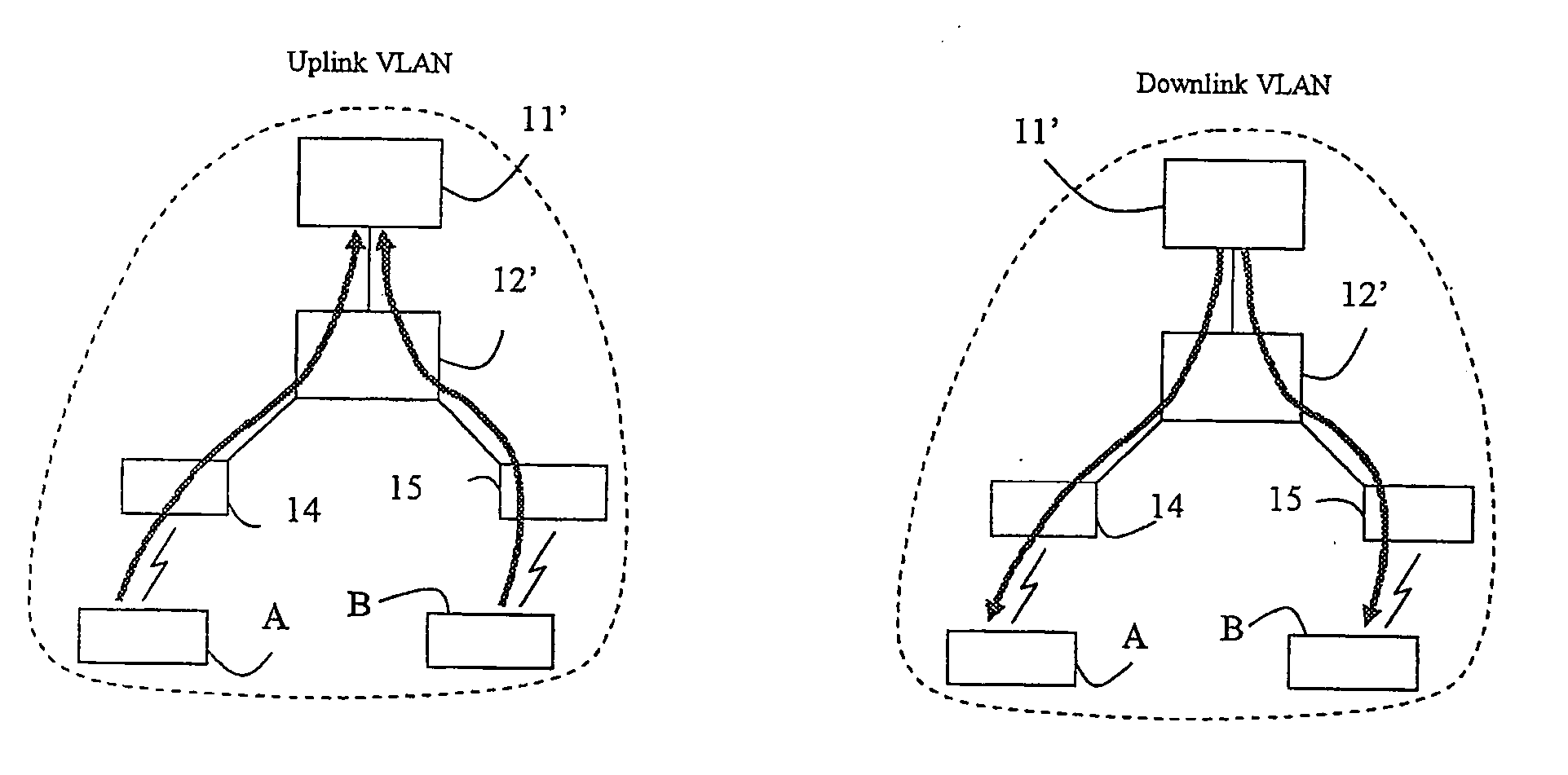
[0066] In this variant only two asymmetric VLANs are used to isolate hosts from each other, irrespective of the number of hosts. This makes the VLAN configuration very simple and scalable.

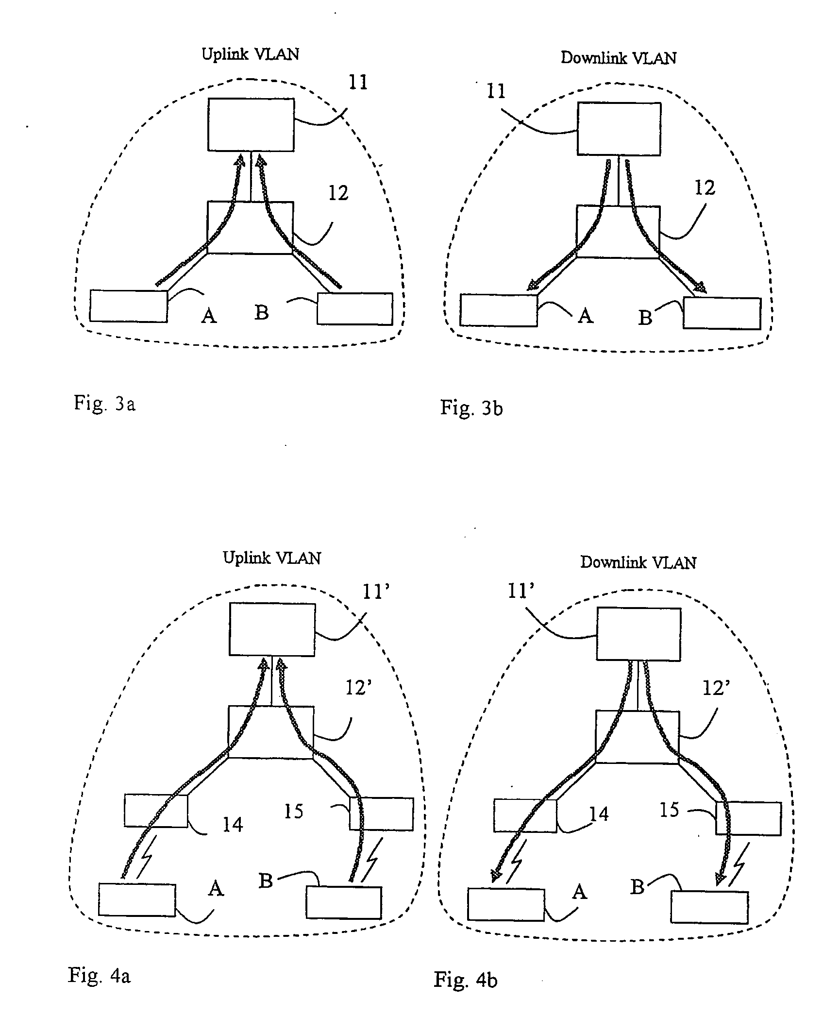
[0067] Of the two asymmetric VLANs one is used for uplink (host to access router) traffic and one is used for downlink (access router to host) traffic. Conceptually the two VLANs can be depicted as in FIGS. 3a and 3b and FIGS. 4a and 4b. FIG. 3a shows schematically the uplink VLAN in a fixed access network. One access router 11 is shown connected to a switch 12. The switch 12 is connected to two hosts, A and B. The arrows show the allowed traffic paths. In this uplink VLAN only uplink traffic from the hosts A, B to the access router 11 is allowed. Furthermore the uplink VLAN is defined such that all traffic received in the switch 12 from the hosts A, B has to be forwarded up to the access router 11, i.e. direct host to host communication is prevented. FIG. 3b shows schematically the downlink V...

second embodiment

ic VLANs

Isolation of Hosts

[0106] In this solution variant the principle for isolation of hosts differ somewhat between WLAN access networks and fixed access networks.

Isolation of Hosts Connected to WLAN Access Networks

[0107] Instead of using a single asymmetric VLAN for uplink traffic, each AP has a dedicated VLAN for uplink traffic in this solution variant for WLAN access networks. The result is that the uplink traffic from all the hosts associated with a certain AP is carried through the VLAN dedicated to the AP. A single asymmetric VLAN is used for all downlink traffic. Having a dedicated VLAN for each AP should not cause any scaling problems, since it is foreseen that the number of APs in an access network will be far less than 4096. Conceptually the VLANs can be depicted as in FIGS. 8a, b and c. An access network comprising one access router 81, one switch 83 connected to the access router 81, a first and a second AP 85, 86 connected to the switch 83 and hosts A and B is s...


PUM


Abstract

A method and an arrangement in an access network for preventing hosts (5;A,B) connected to the access network from communicating directly with each other. Said method comprises the steps of defining Virtual Local Area Networks, VLANs, in switches (3;12;12′;35,36,37;83) such that traffic arriving in the switches from said hosts is forced to an access router (1;11;11′;11″;81) and defining in the switches one asymmetrical downlink VLAN for downlink traffic from the access router to the hosts, said downlink VLAN being common to said hosts. According to the invention the method comprises the further steps of configuring the VLANs such that said hosts connected to the access network belong to the same IP subnet and configuring the access router to perform intra-subnet routing and to be an Address Resolution Protocol proxy.

Description

TECHNICAL FIELD OF THE INVENTION [0001] This invention relates to a method and an arrangement in an access network for preventing hosts connected to the access network from communicating directly with each other. BACKGROUND OF THE INVENTION [0002] The invention is related to the field of Ethernet access networks. Although Ethernet and IEEE 802.3 are not identical, the term “Ethernet” is henceforth somewhat inappropriately used to denote either Ethernet or IEEE 802.3. The access network could be a plain Ethernet network or a combination of a fixed Ethernet network and a wireless part using the corresponding WLAN (Wireless LAN) technology IEEE 802.11 (most likely IEEE 802.11b). The main target for the invention is public access networks, but it could also be applied to corporate wireless access networks. A fixed all-Ethernet access network is illustrated in FIG. 1 and a combined Ethernet and WLAN access network (i.e. a WLAN access network) is illustrated in FIG. 2. The access network ...

Claims


Application Information

Patent Timeline
IPC IPC(8): H04Q7/24H04L12/46H04L12/56H04L29/06H04W12/08
CPCH04L12/2856H04L12/2898H04L12/4641H04L12/4645H04L12/467H04L29/12009H04W12/08H04L45/04H04L61/10H04L63/0272H04L63/08H04L63/1441H04L29/12018H04L61/00
Inventor RUNE, JOHAN
Owner TELEFON AB LM ERICSSON (PUBL)
Why Eureka
Try Eureka