Delay-reduced stall avoidance mechanism for reordering a transport block

Inactive Publication Date: 2006-03-23
NOKIA SOLUTIONS & NETWORKS OY
5 Cites 47 Cited by

AI-Extracted Technical Summary

Problems solved by technology

However, the implementation of the multi-channel SAW ARQ mechanism at L1/MAC layer for the E-DCH may cause a different number of transmission attempts to be required for each data block so that the in-sequence reception of the data blocks at the receiver cannot be assured.
Protocol stalling of the multi-channel SAW ARQ mechanism is a know problem when used in a wireless channel.
However, the timer mechanism can cause significant transmission delays.
One drawback of the timer mechanism is that it will sometimes add unnecessary delay to the Protocol Data Unit (PDU) delivery to the RLC layer, degrading the performance in terms of Servi...

Benefits of technology

[0012] The present invention uses timer and window based stall avoidance mechanisms similar to those used for (HSDPA) (Ref 3GPP TS 25.321 V5.3.0) for the E-DCH due to the introduction of a multiple-channel Stop And Wait Automatic Repeat reQuest (N-channel SAW ARQ). The present invention allows the receiver window to be adapted to the transmitter window by having a more stringent and accurate setting of the stall timer. The timer is activated when a correctly decoded data...

Abstract

A method for implementing a stall avoidance mechanism during uplink transmission of data blocks from transmitter to a receiver includes first determining a missing data block in response to a successful receipt of a received data block at the receiver. Once the missing data block is determined, the receiver requests retransmission of the missing data block. The receiver starts a timer when the request for retransmission is made such that the timer has a time value based on the number of reception attempts of the received data block made by the receiver.

Application Domain

Technology Topic

Image

  • Delay-reduced stall avoidance mechanism for reordering a transport block
  • Delay-reduced stall avoidance mechanism for reordering a transport block
  • Delay-reduced stall avoidance mechanism for reordering a transport block

Examples

  • Experimental program(1)

Example

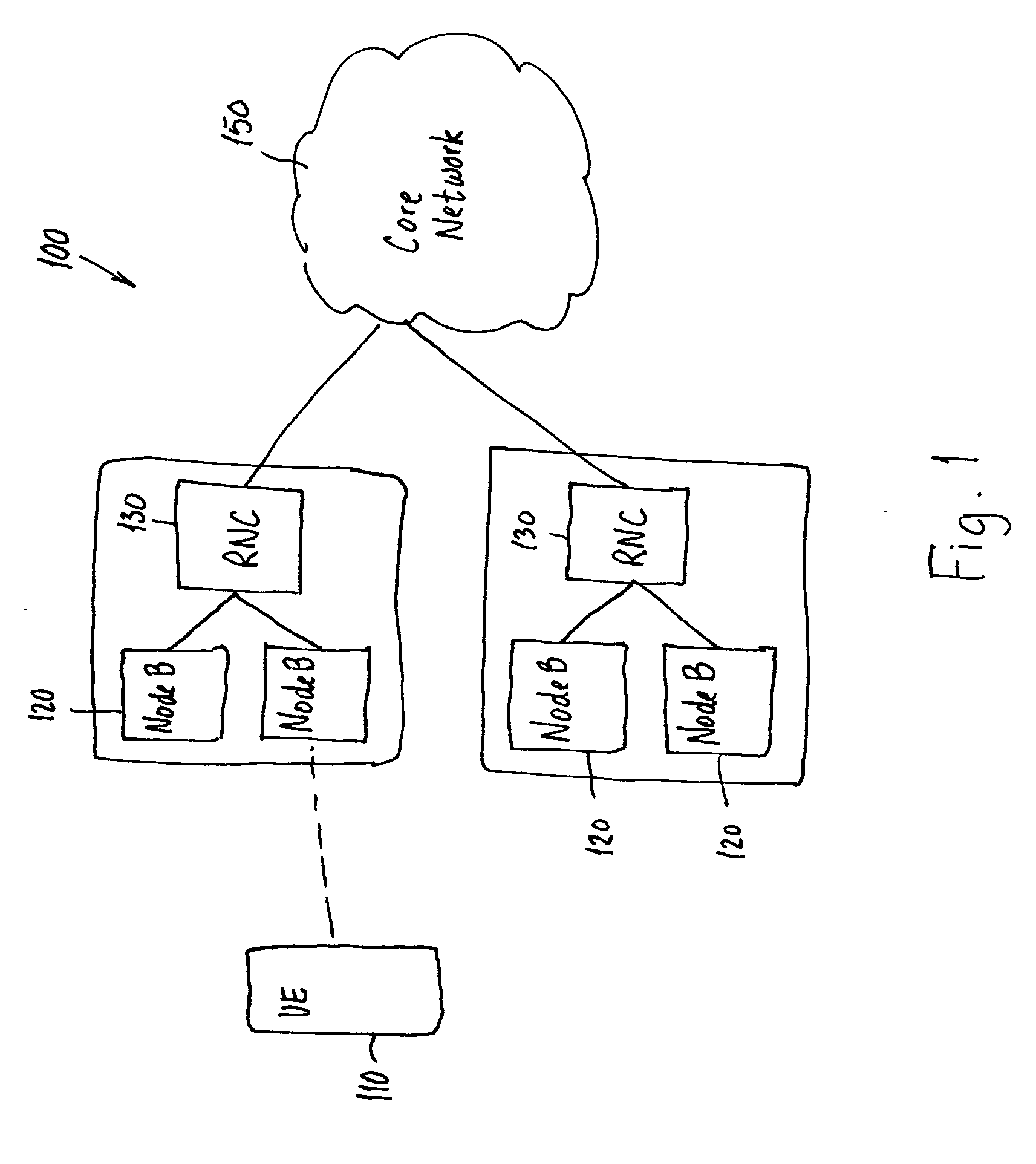
[0050]FIG. 1 is a schematic diagram of an example of a network in which the present invention is implemented. A Radio Access Network (RAN) 100 includes a User Equipment (UE) 110 in communication with at least one base station, i.e., Node B 120, of a plurality of base stations such as Node Bs 120. Each of the Node Bs 120 is connected to a Radio Network Controller (RNC) 130 which is connected to a core network 150. The RNCs 130 communicate with each other and are, e.g., responsible for handover decisions. The present invention relates to uplink transmissions and includes transmissions from a UE 110 to a Node B and transmissions from a Node B 120 to an RNC 130. Each of the UE 110, Node B 120, and RNC 130 include processors for processing data as described below. The processors may include specifically designed hardware or may be arranged to run programs for performing the functions described below.
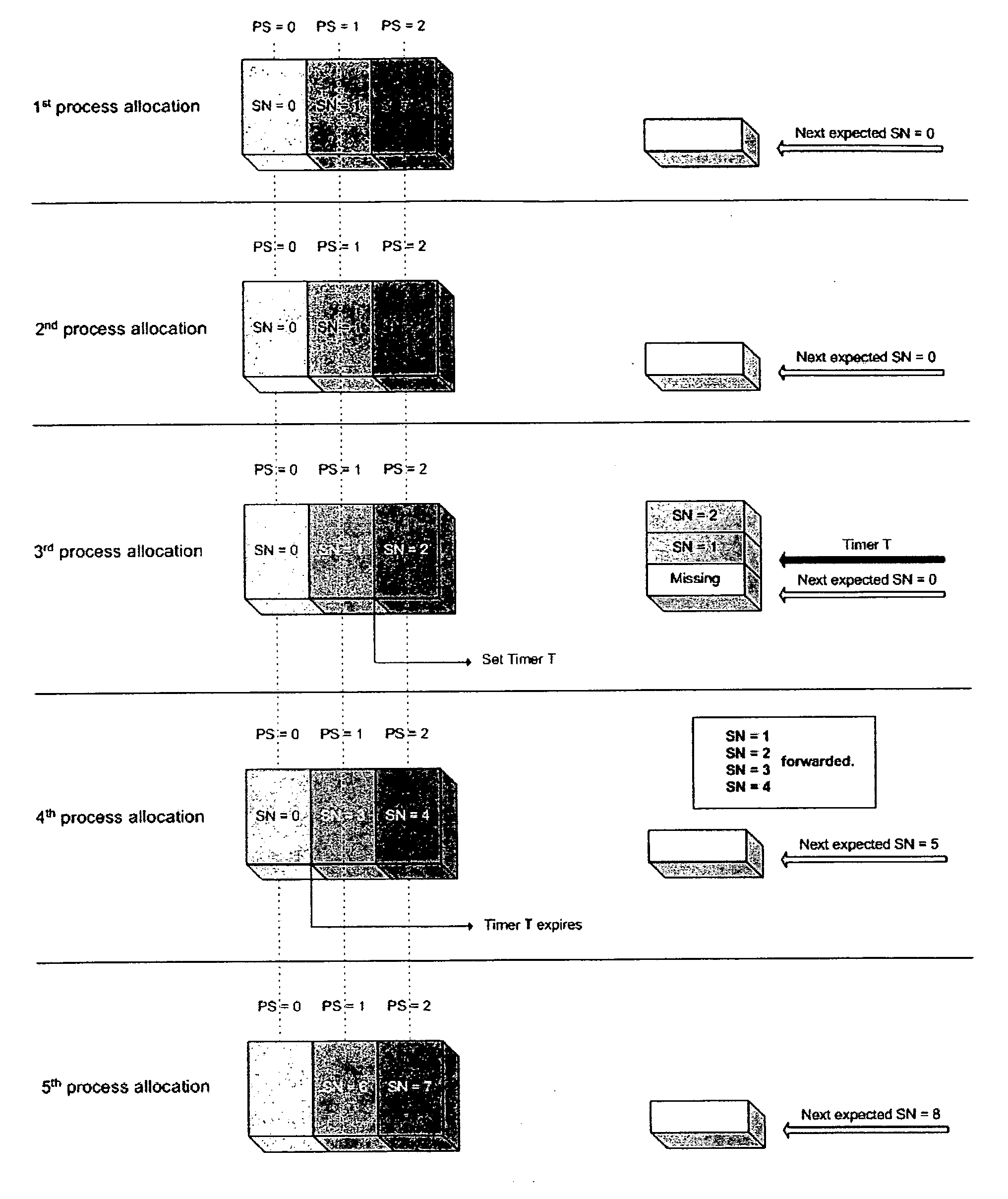
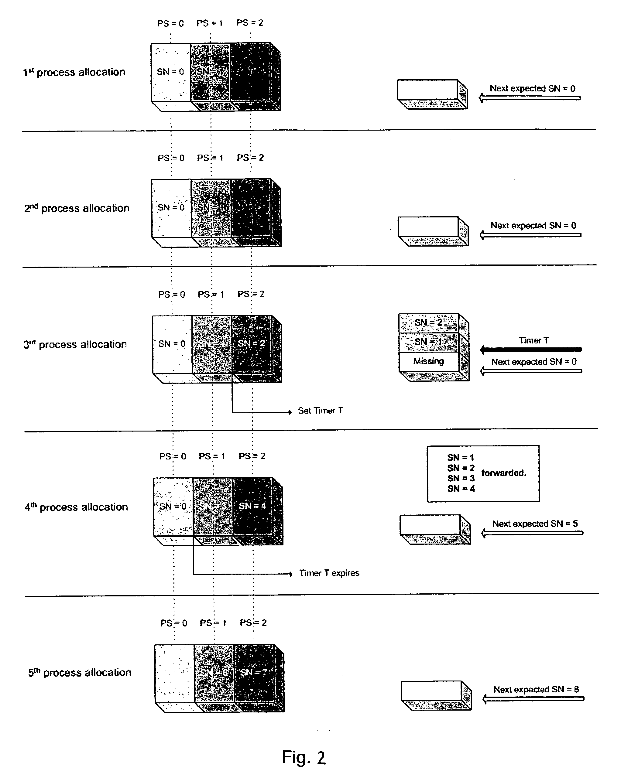
[0051]FIG. 2 shows allocations for the first through fifth transmissions of three synchronous processes PS 0, 1, 2 in an uplink receiver according to an example using the method of the present invention. According to the illustrative example, there are a maximum of four transmission attempts per process for each data block. According to FIG. 2, all three processes PS 0, 1, 2 fail to correctly decode the datablocks SN 0, 1, 2, respectively, in the first two process transmissions. On the third process transmission, SN 1, 2 are correctly decoded and SN 0 is not correctly decoded. Accordingly, SN 1, 2 are buffered in the reordering queue. Once SN 1 is received, it is determined that SN 0 is missing and a timer T is started. The timer is set according to the following equation [1]:
Timer=Max(T_Initial−[(N*TTI)*(Reception_Number−1)],0)  [1]
wherein:
[0052] T_Initial—is the timer setting from upper layer signaling;
[0053] N—is the number of ARQ processes;
[0054] TTI—is the TTI length; and
[0055] Reception_Number—is the number of reception attempts of the correctly received block.
[0056] T_Initial is defined by the following equation [2]:
T_Initial=[(Max_Retransmissions_Number*N)−1]*TTI [2]
wherein:
[0057] Max_Retransmissions_Number—is the maximum number of retransmissions of a TB;
[0058] N—is the number of ARQ processes; and
[0059] TTI—is the TTI length.
[0060] In the present example, there are a maximum of four transmission attempts per process for each data block. Accordingly, the maximum number of retransmissions is three. There are three ARQ processes (PS 0, 1, 2). Using Equation [2], the timer setting T_Initial is ((3*3)−1)*TTI=8TTI.
[0061] In the above example, SN 1 is correctly received after the third reception attempt. According to Equation [1], the timer is set to 8TTI−(3*TTI)*(3-1)=2TTI.
[0062] In the fourth transmission in FIG. 2, processes PS 0, 1, 2 transmit SN 0, 3, 4. Only SN 3, 4 are correctly decoded. Since the Timer is active for only two TTIs, the timer expires in the fourth transmission and SN 1, 2, 3, and 4 are forwarded. Processes PS 0, 1, 2, transmit SN 5, 6, 7 in the fifth transmission.
[0063]FIG. 3 shows the allocations of the third through the sixth transmissions of processes PS 0, 1, 2 using the same data as the example in FIG. 2 according to the prior art without using the inventive method. The allocations of the first and second process allocation are the same as those shown in FIG. 2. Since the timer is not limited or reduced, as in the present invention, the timer is active in this example, for eight TTIs (T_Initial is not reduced) and expires in the sixth transmission. The blocks SN 1, 2, 3, 4, 5, 6, 7, 8, 9, and 10 are forwarded at the sixth transmission.
[0064]FIG. 4 is a table showing the Transport Block delay including reordering with timer stall avoidance mechanism. The inventive method delay is based on FIG. 2 and the prior art delay is based on FIG. 3. The invented method delay and prior art delay columns show the TB delay in number of TTIs, split in two components, the transmission delay+the timer stall avoidance mechanism delay. The two last columns show the respective delay gain per TB for 10 and 2 ms TTI length that the proposed invention achieves.
[0065]FIG. 5 is a flowchart introducing the high level description of the reordering mechanism including improved timer stall avoidance feature. In step 510, the transport block (TB) with a Cyclic Redundancy Code (CRC) result is received, e.g., at the RNC from the Node B via Iub. Reordering signaling is then retrieved for the current reception, e.g., the SN, queue ID for the received TB, step 512. The number of reception attempts is determined for the TB after the missing block, i.e., the TB that triggers the activation of the timer, step 514. In step 516, the queue is then reordered based on the reordering signaling determined in step 512. In step 418, the stall avoidance timer is managed in accordance with the number of reception attempts determined in step 514.
[0066]FIG. 6 is a flowchart of the proposed new timer stall avoidance setting. In step 610, the number of reception attempts of the correctly received TB which triggers the activation of the timer setting, the timer initial setting T_Initial and the air interface delay N*TTI are determined. As described above, N is the number of ARQ processes and TTI is the TTI length. The timer initial setting T_Initial is given in Equation [2]. In step 620, the timer is set in accordance with Equation [1].
[0067] Thus, while there have shown and described and pointed out fundamental novel features of the invention as applied to a preferred embodiment thereof, it will be understood that various omissions and substitutions and changes in the form and details of the devices illustrated, and in their operation, may be made by those skilled in the art without departing from the spirit of the invention. For example, it is expressly intended that all combinations of those elements and/or method steps which perform substantially the same function in substantially the same way to achieve the same results are within the scope of the invention. Moreover, it should be recognized that structures and/or elements and/or method steps shown and/or described in connection with any disclosed form or embodiment of the invention may be incorporated in any other disclosed or described or suggested form or embodiment as a general matter of design choice. It is the intention, therefore, to be limited only as indicated by the scope of the claims appended hereto.

PUM

no PUM

Description & Claims & Application Information

We can also present the details of the Description, Claims and Application information to help users get a comprehensive understanding of the technical details of the patent, such as background art, summary of invention, brief description of drawings, description of embodiments, and other original content. On the other hand, users can also determine the specific scope of protection of the technology through the list of claims; as well as understand the changes in the life cycle of the technology with the presentation of the patent timeline. Login to view more.

Similar technology patents

Classification and recommendation of technical efficacy words

Why Eureka
Try Eureka