Method and apparatus for the production of radioisotopes

a radioisotope and production method technology, applied in electrical apparatus, chemical to radiation conversion, nuclear targets, etc., can solve the problems of target foil rupture or otherwise failure, sample material and target foil being subject to elevated pressure, and target foil heating being subject to failur

Inactive Publication Date: 2006-03-23
HOUSTON CYCLOTRON PARTNERS
View PDF24 Cites 83 Cited by
  • Summary
  • Abstract
  • Description
  • Claims
  • Application Information

AI Technical Summary

Benefits of technology

[0016] In one aspect of the invention, a target system is provided. The target system includes a beam path for receiving a particle beam. A target body is positioned along the beam path and includes a target chamber and a target foil. The target chamber is operable for housing the sample material. The target foil is positioned proximate the target chamber and is operable for holding the sample material in t

Problems solved by technology

Unfortunately, during operation, the window foils of the target system absorb a portion of the beam power, and this energy is converted into heat.
In addition, the sample material and the target foil are usually subjected to elevated pressures during irradiation.
This stress may cause the target foil to rupture or otherwise fail during irradiation.
Unfortunately, if the thickness of the target f

Method used


Image

  • Method and apparatus for the production of radioisotopes
  • Method and apparatus for the production of radioisotopes
  • Method and apparatus for the production of radioisotopes

Examples


Embodiment Construction

[0022] Illustrative embodiments of the invention are described below. In the interest of clarity, not all features of an actual implementation are described in this specification. It will of course be appreciated that in the development of any such actual embodiment, numerous implementation-specific decisions must be made to achieve the developers' specific goals, such as compliance with system-related and business-related constraints, which will vary from one implementation to another. Moreover, it will be appreciated that such a develop-ment effort might be complex and time-consuming, but would nevertheless be a routine undertaking for those of ordinary skill in the art having the benefit of this disclosure.

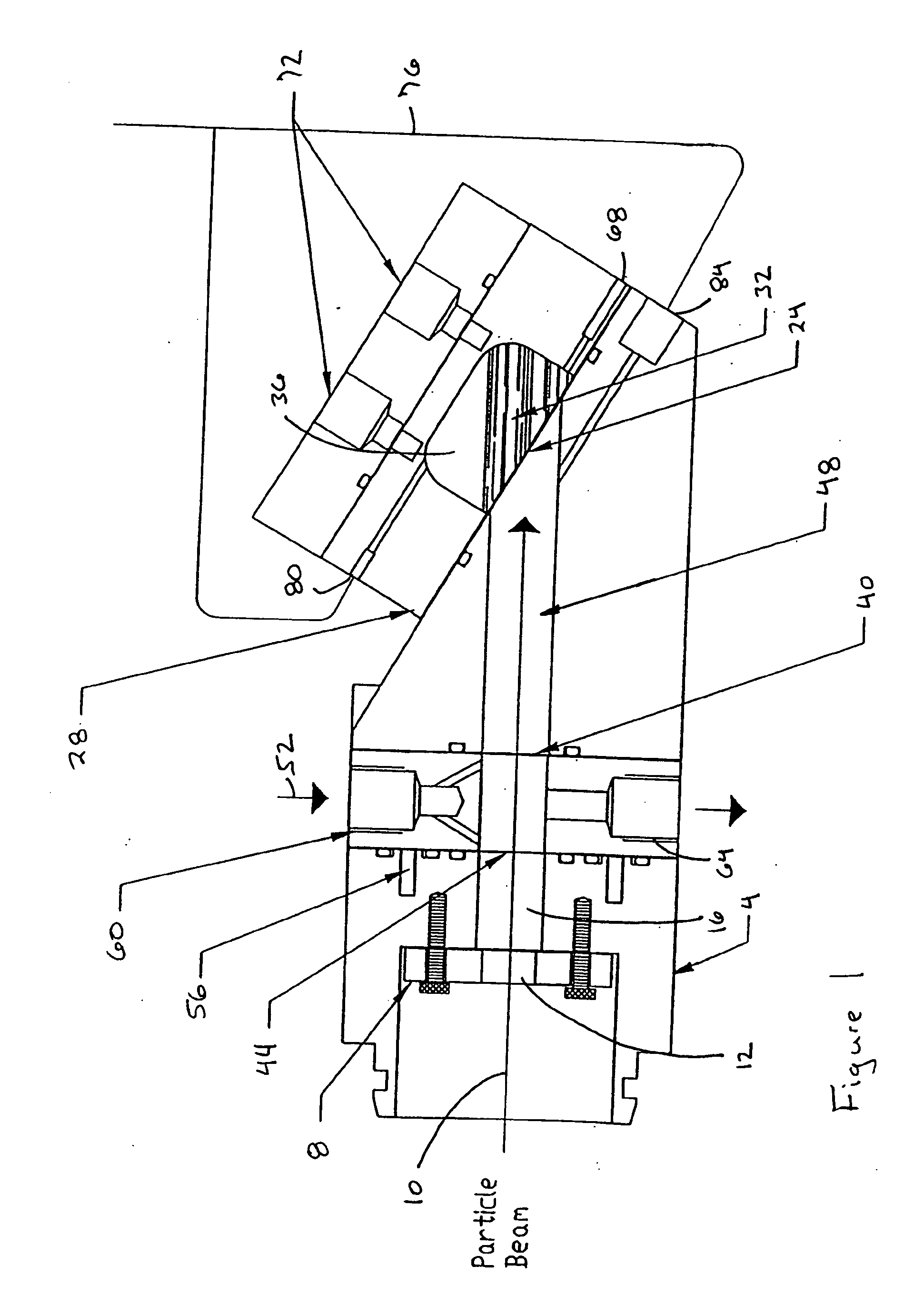
[0023] Referring to FIG. 1, a target system 4 in accordance with one embodiment of the present invention is shown. The target system 4 is operable with a particle beam accelerator (not shown) to produce radioisotopes. In this illustrative example, the target system 4 is couple...


PUM


Abstract

A target system includes a beam path for receiving a particle beam and a target chamber for housing a sample material. A target foil is operable for holding the sample material in the target chamber. A pressure cell is formed along a portion of the beam path between the target foil and a pressure foil. When irradiating the sample material with the particle beam, the pressure inside the target chamber and the pressure cell is increased and maintained at substantially the same pressure. A method includes inserting a sample material into a target chamber of a target system. The target system includes a pressure cell formed along a portion of a beam path between a pressure foil and a target foil, adjacent the target chamber. The pressure cell and the target chamber are pressurized and maintained at substantially the same pressure. The sample material is irradiated to produce a radioisotope.

Description

BACKGROUND OF THE INVENTION [0001] 1. Field of the Invention [0002] This invention relates generally to the production of radioisotopes, and, more particularly, to a target system for irradiating a sample material by an accelerated particle beam. [0003] 2. Description of the Related Art [0004] A radioisotope is an unstable element that releases radiation (energy in the form of particles or electromagnetic waves), while it decays into a stable element. The decay rate is usually referred to as the half-life of the element. Radioisotopes may be used in a number of different applications. Medical applications of radioisotopes may include, for example, imaging and measuring of physiological processes or the treatment of cancer. [0005] Position Emission Tomography (PET) is one particular imaging application that uses radioisotopes. A PET procedure generally includes labeling a radiopharmaceutical with a radioactive isotope and then administering the radiopharmaceutical to a patient. The r...

Claims


Application Information

Patent Timeline
IPC IPC(8): G21G1/10
CPCH05H6/00G21G1/10
Inventor GONZALEZ LEPERA, CARLOS E.STRANGIS, SAVERIO R.
Owner HOUSTON CYCLOTRON PARTNERS
Why Eureka
Try Eureka