Substrate crack inspection apparatus and substrate crack inspecting method

a substrate crack and inspection apparatus technology, applied in the direction of instruments, electrical transducers, transducer casings/cabinets/supports, etc., can solve the problems of reducing mechanical strength, troublesome facilities, and causing defects, and achieve high-reliability substrate crack inspection.

Inactive Publication Date: 2006-03-23
SHARP KK
View PDF0 Cites 6 Cited by
  • Summary
  • Abstract
  • Description
  • Claims
  • Application Information

AI Technical Summary

Benefits of technology

[0010] The present invention has been made in view of such circumstances and provides an apparatus and a

Problems solved by technology

In processing the silicon wafer in each step, a defect will be caused.
The defect may be aggravated in a later step to finally lead to in some cases a failure and in other cases a remarkably reduction in mechanical strength.
In the case of wafer failure or the like, troubles in facilities or a decrease in operating rate in the manufacturing steps may be resulted, while in the case of a remarkable reduction in mechanical strength, a decrease in electric power generation capability may be resulted.
In the prior art disclosed in this publication, since an apparatus for applying a stress to the substrate is necessary, the manufacturing equipment is complicated, and there exists a problem that production efficiency declines.
Therefore, there are many spacial and mechanical restrictions in using this apparatus in the present production process.
Further, due t

Method used


Image

  • Substrate crack inspection apparatus and substrate crack inspecting method
  • Substrate crack inspection apparatus and substrate crack inspecting method
  • Substrate crack inspection apparatus and substrate crack inspecting method

Examples


first embodiment

1-1. First Embodiment

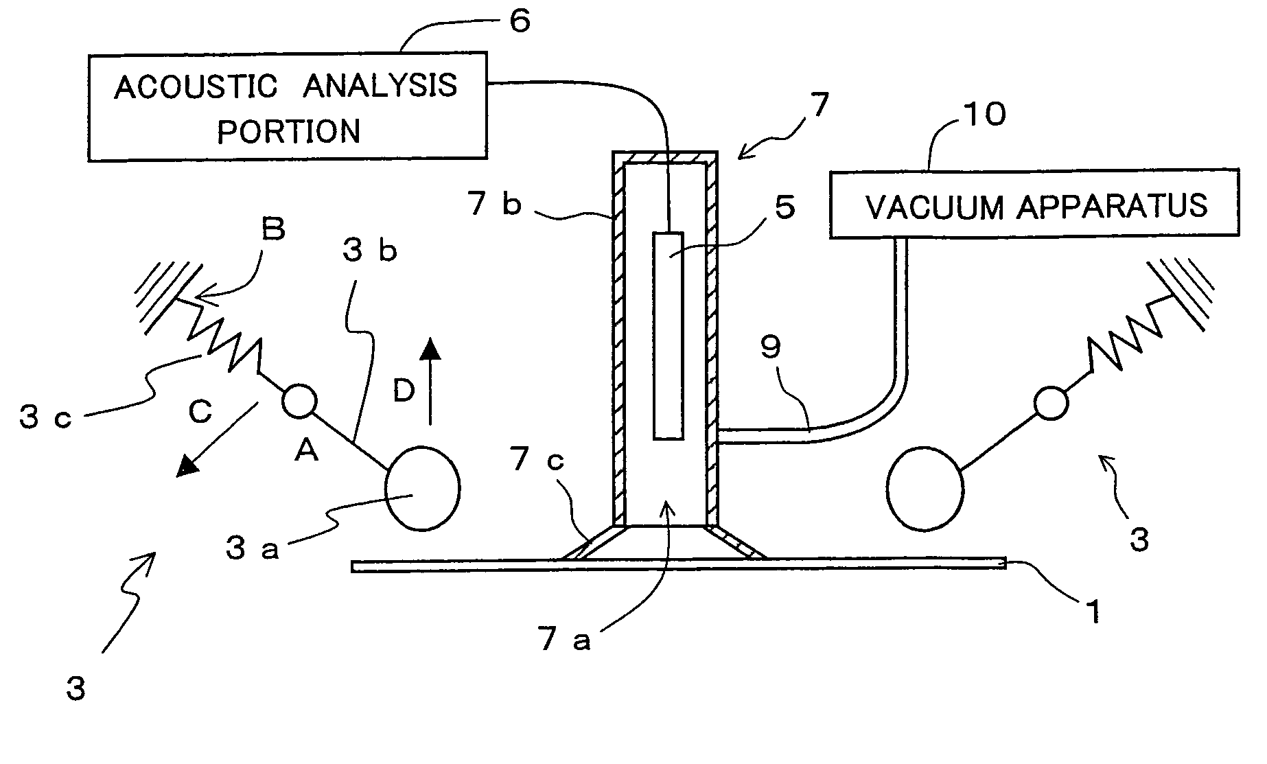
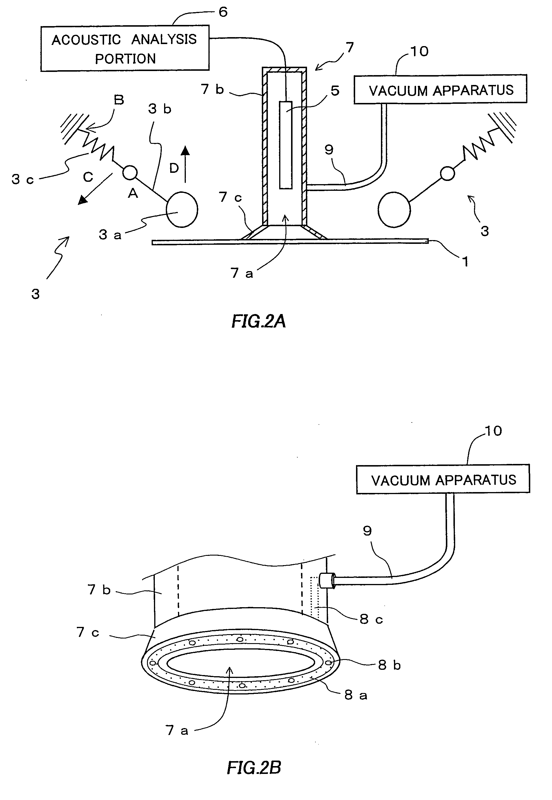
[0028] A substrate crack inspection apparatus according to a first embodiment in the first aspect of the present invention comprises: a striking portion for producing a sound by providing a vibration to a substrate; a first microphone for capturing the sound produced by the striking portion; and an acoustic analysis portion for carrying out an acoustic analysis of the sound captured by the first microphone to determine a first power spectrum and judging whether or not a substrate crack exists based on a spectral intensity of a predetermined frequency region, the first microphone being covered with a cover having an opening facing the substrate.

[0029] The striking portion strikes the substrate by using a driving force by a motor or a hydraulic cylinder or a spring elastic force. The striking portion is preferably formed of a synthetic rubber whose Shore is approximately 40-60. As the acoustic analysis portion, an element having a program for carrying out, by use...

second embodiment

1-2. Second Embodiment

[0044] A substrate crack inspection apparatus according to a second embodiment in the first aspect of the present invention comprises: a plurality of striking portions each for producing a sound by providing a vibration to a substrate; a first microphone for capturing the sounds produced by the striking portions; and an acoustic analysis portion for carrying out an acoustic analysis of the sounds captured by the first microphone to determine a plurality of first power spectra, statistically analyzing spectral intensities of a predetermined frequency region for the plurality of obtained first power spectra and judging whether or not a substrate crack exists based on the result of the statistic analysis, the first microphone being covered with a cover having an opening facing the substrate.

[0045] The substrate crack inspection apparatus according to the present embodiment comprises a plurality of striking portions. For explanations of the remaining components, r...


PUM


Abstract

The present invention aims to provide a substrate crack inspection apparatus comprising: a striking portion for producing a sound by providing a vibration to a substrate; a first microphone for capturing the sound produced by the striking portion; an acoustic analysis portion for carrying out an acoustic analysis of the sound captured by the first microphone to determine a first power spectrum and judging whether or not a substrate crack exists based on a spectral intensity of a predetermined frequency region; and eliminating means for an eliminating the effect of external noise on the produced sound.

Description

CROSS-REFERENCE TO RALATED APPLICATION [0001] This application is related to Japanese applications Nos. 2004-245536 and 2004-277303, filed on Aug. 25, 2004 and Sep. 24, 2004 whose priorities are claimed under 35 USC § 119, the disclosures of which are incorporated by reference in their entirety. BACKGROUND OF THE INVENTION [0002] 1. Field of the Invention [0003] The present invention relates to a substrate crack inspection apparatus and a substrate crack inspecting method. More particularly, the present invention relates to an apparatus and a method that permit highly reliable substrate crack inspection even under the presence of external noise. [0004] 2. Description of Related Art [0005] As a conventional method for detecting a microcrack, known is a method of previously applying to a substrate a stress substantially the same as a stress that the substrate receives at the time of a predetermined processing, adding another shock to the substrate, and detecting whether or not damage ...

Claims


Application Information

Patent Timeline
IPC IPC(8): H04R1/02H04R3/00
CPCG01N29/045G01N29/32G01N29/223
Inventor YAGI, KATSUYUKI
Owner SHARP KK
Why Eureka
Try Eureka