Lubricant distribution weir for lubricating moving machine elements

a technology of moving machine elements and distribution weirs, which is applied in the direction of machines/engines, mechanical equipment, couplings, etc., can solve the problems of unwieldy cost and difficulty in precisely controlling the geometry of each groove, and increasing machining difficulty and cos

Inactive Publication Date: 2006-03-23
GENERAL ELECTRIC CO
View PDF9 Cites 52 Cited by
  • Summary
  • Abstract
  • Description
  • Claims
  • Application Information

AI Technical Summary

Benefits of technology

[0011] A device for lubricating axially mounted rotating aircraft engine parts when rotating is provided. It comprises a circumferential lubricant reservoir for supplying lubricant to the parts to be lubricated having a first side and a second side, the first side having a deeper wall height than the second side, and a top side disposed closer to the axis of rotation than a bottom side that is disposed further f...

Problems solved by technology

Using existing machining technology, it is costly and difficult to exactly control the geometry of each groove since each groove and its intersection with the lubricant reservoir must be individually machined to exacting tolerance.
Machining difficulty and cost become even m...

Method used


Image

  • Lubricant distribution weir for lubricating moving machine elements
  • Lubricant distribution weir for lubricating moving machine elements
  • Lubricant distribution weir for lubricating moving machine elements

Examples


Embodiment Construction

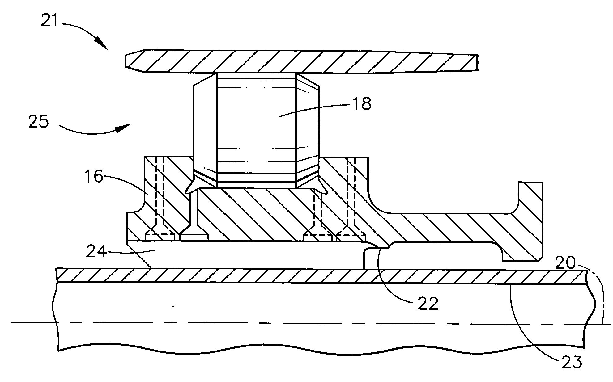
[0023] As used herein, a lubricant is a fluid that is used to cool or reduce friction or to both cool and reduce friction in moving parts. Accordingly, lubricating or performing lubrication refers to the act of cooling or reducing friction or to the act of cooling and reducing friction in moving parts.

[0024] A circumferential lubricant reservoir is filled with lubricant by means external to the reservoir. For example, in one embodiment the reservoir can be filled from a series of scoops mounted on a rotating element that move lubricant from a lubricant sump into the reservoir. The reservoir can be machined into or mounted on a rotating element of machinery but is disposed at a constant radius and in a circumferential manner around the axis of rotation of the rotating element. That is, the reservoir is disposed about the axis of rotation in a circular arc centered on the axis of rotation of the rotating machine element. When rotating, lubricant in the reservoir is subjected to the c...


PUM


Abstract

A device and method for uniformly providing lubricant to rotating machine parts is provided. The device comprises an axially mounted rotating circumferential lubricant reservoir with a weir comprising one side of the lubricant reservoir. The reservoir and weir are disposed at uniform radius and circumferentially about an axis of rotation causing lubricant added to the reservoir to flow uniformly over the weir about the circumference of the weir when the device is in high speed rotational motion. Because of the uniform flow of lubricant over the top of the weir around the circumference of the weir, lubricant can be directed to machine parts requiring lubrication in a uniform manner around the circumference of the moving device.

Description

BACKGROUND OF THE INVENTION [0001] This application relates to tribology in rotating machinery. [0002] When a mass experiences circular motion about an axis of rotation, the mass will fly off in a tangent to the circumference of rotation unless it is constrained to move in circular motion by a centripetal force. An example of this is a mass on the end of a string in circular motion about an axis of rotation. The string provides a centripetal force on the mass constantly accelerating it radially, and constraining it to move in a circle. If the string is lengthened without changing the linear speed of the mass, the force provided by the string is reduced, but the circumference of rotation is increased, and the mass stays in circular motion about the axis of rotation. From another aspect, if the angular speed of the mass is held constant, the centripetal acceleration of the mass increases as the string is lengthened, and the force provided by the string is greater. [0003] The fundament...

Claims


Application Information

Patent Timeline
IPC IPC(8): F16C33/02F16C19/00
CPCF01D25/18F16C19/26F16D3/06F16C33/6674F16C33/6677F16C33/6651F16C2360/23F16C33/586
Inventor WILTON, STEPHEN ANTHONYFANG, NINGTHEMUDO, RAMONWHITFORD, DAVID SCOTTKINNAIRD, RAY HARRISFISHER, KENNETH LEE
Owner GENERAL ELECTRIC CO
Why Eureka
Try Eureka