Electronic imaging device

a technology of electronic imaging and sound, which is applied in the direction of instruments, television systems, exposure control, etc., can solve the problem that the operator cannot recognize the operation state of the excitation mechanism based on the operation sound, and achieve the effect of effective dust removal operation, quiet dust removal operation, and convenient us

Active Publication Date: 2006-03-23
OM DIGITAL SOLUTIONS CORP
View PDF3 Cites 11 Cited by
  • Summary
  • Abstract
  • Description
  • Claims
  • Application Information

AI Technical Summary

Benefits of technology

[0009] Accordingly, an operator of the electronic imaging device can correctly recognize whether or not the mechanism to remove the dust is operating. Since generation of sound is not required in the recognition of the operation, quiet operation recognition is possible without any erroneous recognition of another operation sound.
[0016] According to the present invention, the operator can effectively perform the dust removing operation in the electronic imaging device with assistance of the clear display of the dust removing operation. Since the notification is not performed with the sound, quiet dust removal operation can be achieved. Consequently, there can be provided an electronic imaging device, as represented by an electronic camera, which is easy to use.

Problems solved by technology

Usually in a case where the dustproof filter is vibrated by such excitation mechanism, when a vibration frequency exceeds a human audio region, the operator cannot recognize the operation state of the excitation mechanism based on the operation sound.

Method used


Image

  • Electronic imaging device
  • Electronic imaging device
  • Electronic imaging device

Examples


Embodiment Construction

[0037] Preferred embodiments of the invention are described below with reference to the accompanying drawings.

[0038] An electronic imaging device of the present invention will be described hereinafter specifically. The device has a dust control function for an imaging element unit which obtains an image signal by photoelectric conversion. Here, an example will be described as an improved technology relating to dust control for an electronic camera (hereinafter referred to simply as the “camera”). Specifically, one embodiment of a lens-interchangeable single lens reflex electronic camera (digital camera) will be described with reference to FIGS. 1 to 20.

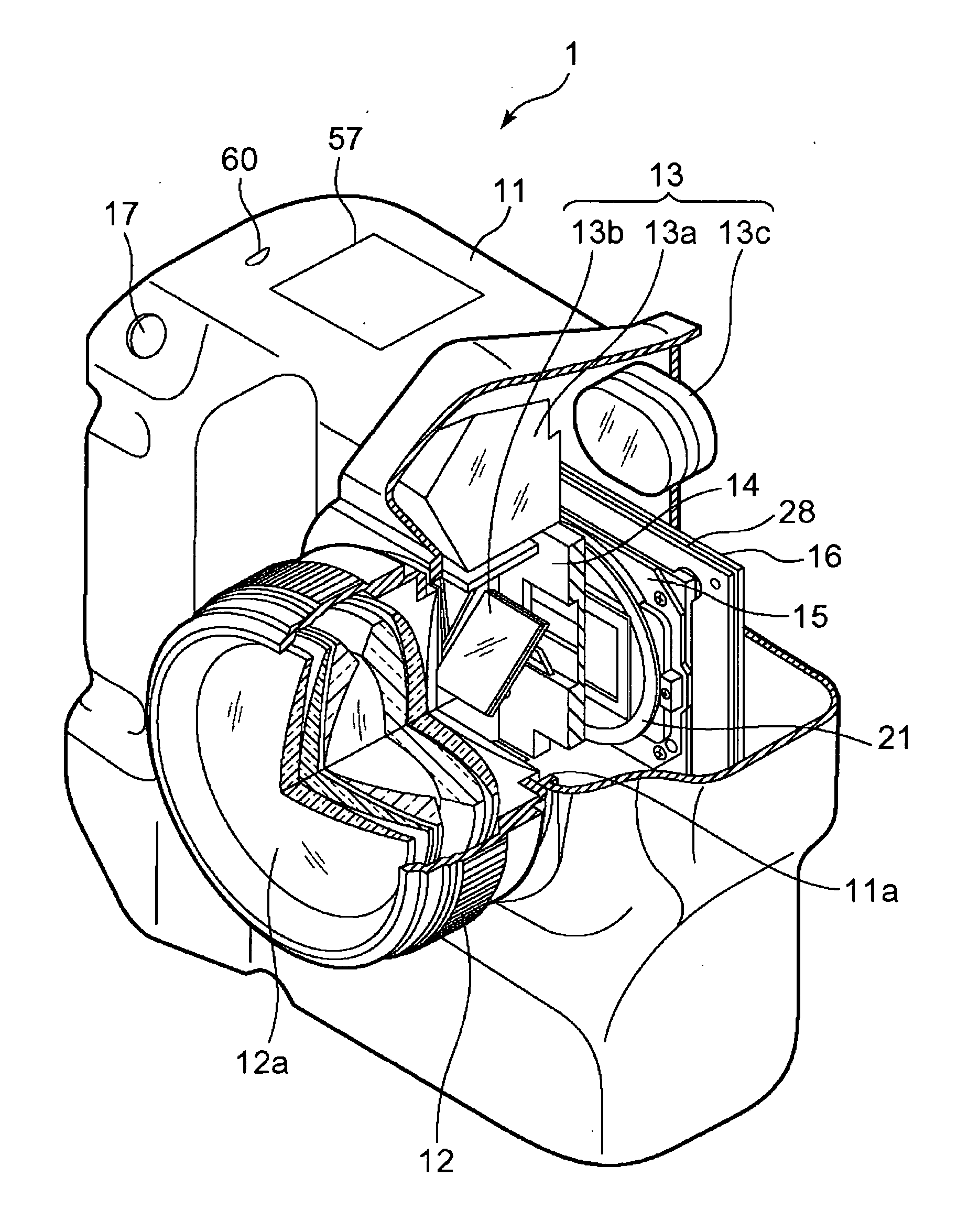
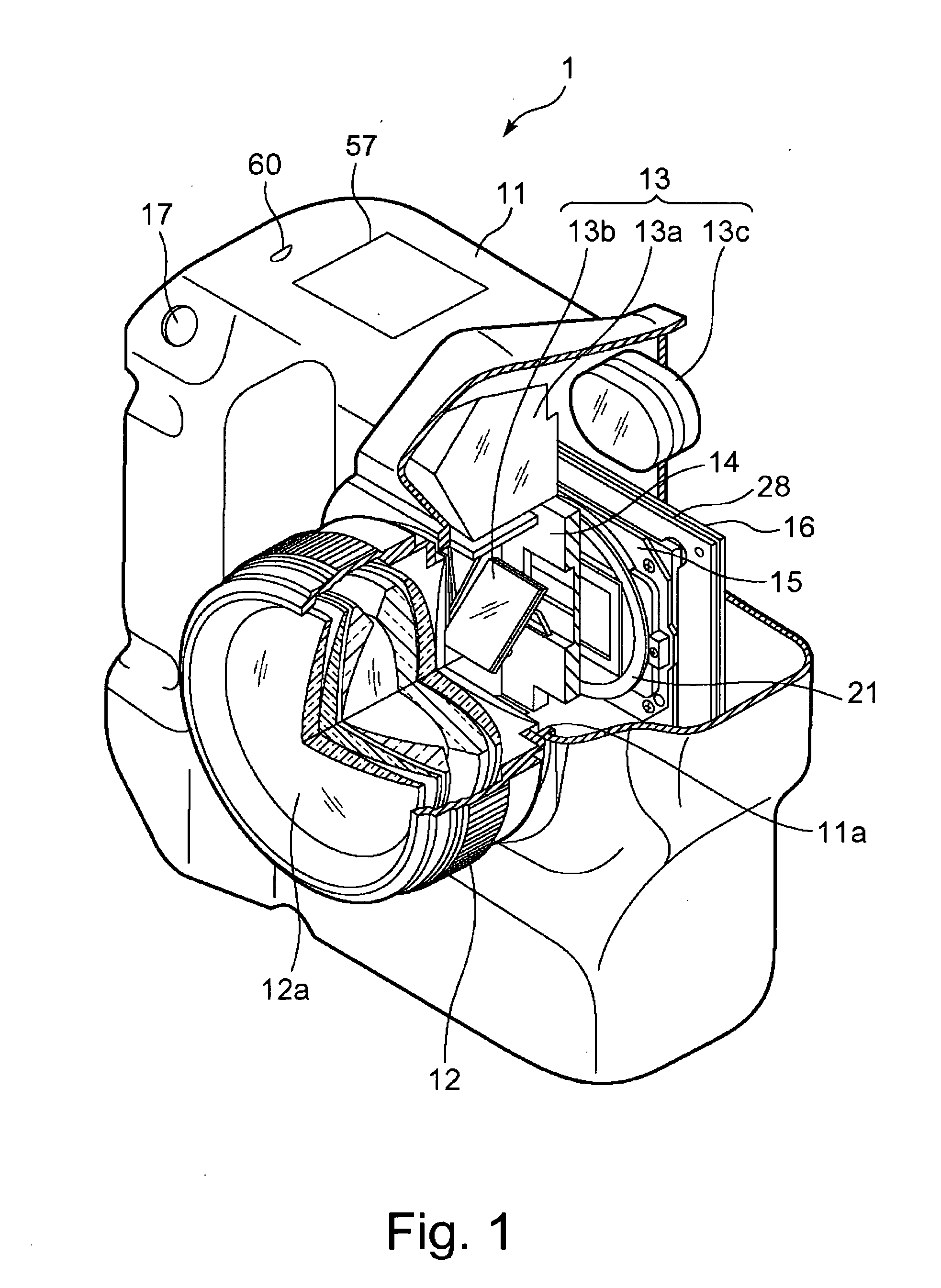
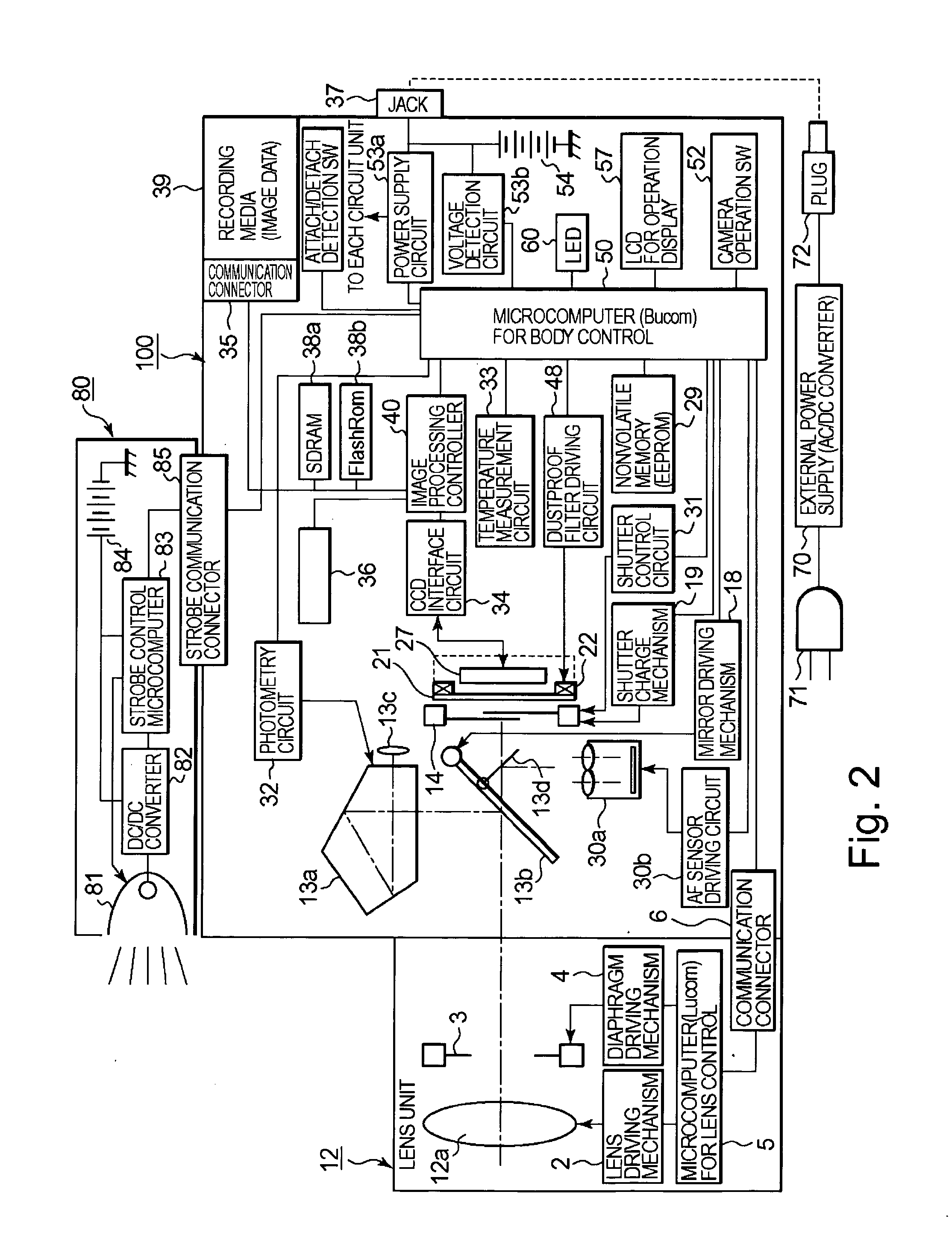
[0039] First, a schematic constitution of the camera of the present embodiment will be described. FIGS. 1 and 2 show the constitution of a camera 1 according to the present embodiment. FIG. 1 is a partially cut perspective view of the camera 1 schematically showing an internal mechanical structure of the camera 1, and FIG. 2 is a bl...


PUM


Abstract

There is disclosed an electronic imaging device having an imaging element, a mechanism which removes dust attached to the imaging element or an optical element disposed in front of the imaging element, and a display section which displays that at least the mechanism is operating. Consequently, an operator of the electronic imaging device can exactly recognize whether or not the mechanism to remove the dust is operating. Examples of the mechanism which removes the dust include an excitation mechanism which vibrates a dustproof filter disposed in front of the imaging element, a mechanism which removes the dust by a gas flow and the like.

Description

CROSS-REFERENCE TO RELATED APPLICATION [0001] This application is based upon and claims the benefit of priority from prior Japanese Patent Application No. 2004-276053, filed Sep. 22, 2004, the entire contents of which is incorporated herein by reference. BACKGROUND OF THE INVENTION [0002] 1. Field of the Invention [0003] The present invention relates to an electronic imaging device provided with an imaging element for outputting an image signal corresponding to light irradiating a photoelectric conversion surface. Examples of this electronic imaging device include a lens-interchangeable single lens reflex digital camera. [0004] 2. Description of the Related Art [0005] In recent years, there has been generally put to practical use a so-called “lens-interchangeable” type of digital camera constituted in such a manner that a plurality of types of imaging optical systems are selectively usable in a single camera main body. For example, the single lens reflex type of digital camera has a...

Claims


Application Information

Patent Timeline
Patent Type & Authority Applications(United States)
IPC IPC(8): G03B17/00
CPCH04N5/217H04N5/23293H04N5/2253H04N23/52H04N23/81H04N23/55H04N23/54H04N23/633
Inventor KAWAI, SUMIO
Owner OM DIGITAL SOLUTIONS CORP
Why Eureka
Try Eureka