Method and apparatus for positional error correction in a robotic pool systems using a cue-aligned local camera

a robotic pool and cue-aligned technology, applied in the field of robotic pool games, can solve the problems of limiting the accuracy of the camera, the resolution limitation of the sensor, and the positioning accuracy of such systems, and achieve the effect of improving the positioning error of the robotic devi

Inactive Publication Date: 2006-03-23
GREENSPAN MICHAEL
View PDF0 Cites 75 Cited by
  • Summary
  • Abstract
  • Description
  • Claims
  • Application Information

AI Technical Summary

Benefits of technology

[0011] The invention may use a local camera, mounted on or near the robotic end-effector in a fixed relationship with the cue, to improve the positioning error of the robotic device prior to placing a shot. By comparing the ball locations...

Problems solved by technology

The cue sports demand a high degree of positional accuracy when placing a shot, and one of the main challenges of a robotic system is to position the cue to the desired location with sufficient accuracy.
Whereas mechanical devices can be positioned very precisely, both sensor errors and robot calibration contribute to limitations to positioning accuracy of such systems.
In the above cases where overhead cameras are the primary sensor to resolve position, a limitation to accuracy is sensor resolution.
Radial distortions in the optical systems also limit the accuracy of the cameras.
A further limitation is that, from the overhead vantage, the table appears as a 2-D plane, and vertical displacements of the cue (i.e., normal to the camera place) cannot be perceived....

Method used


Image

  • Method and apparatus for positional error correction in a robotic pool systems using a cue-aligned local camera
  • Method and apparatus for positional error correction in a robotic pool systems using a cue-aligned local camera
  • Method and apparatus for positional error correction in a robotic pool systems using a cue-aligned local camera

Examples


Embodiment Construction

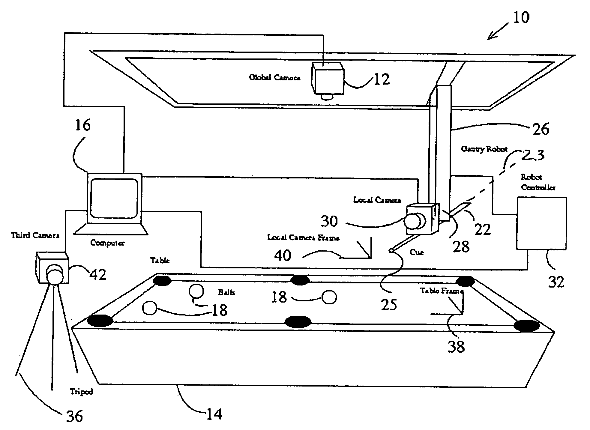
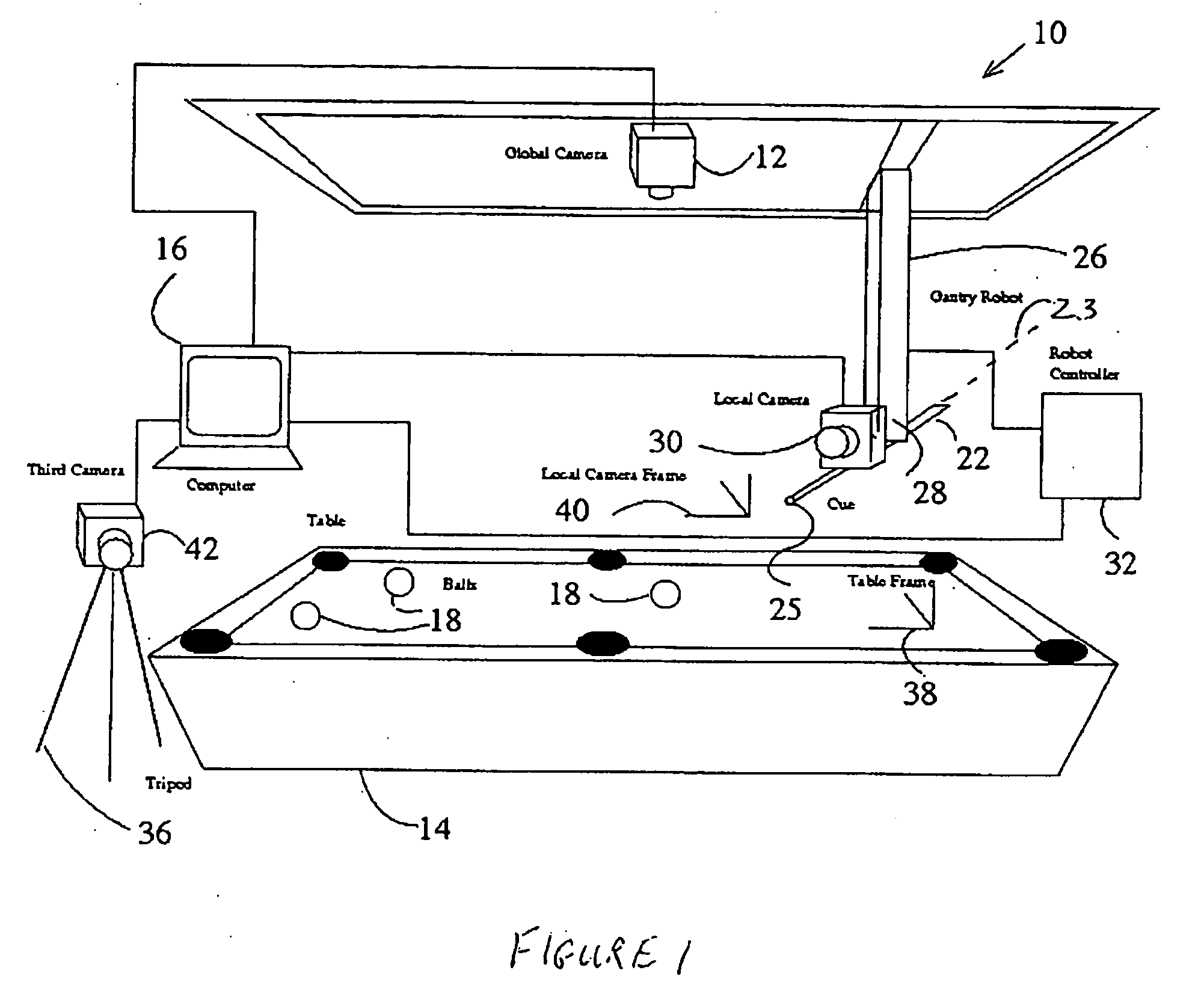
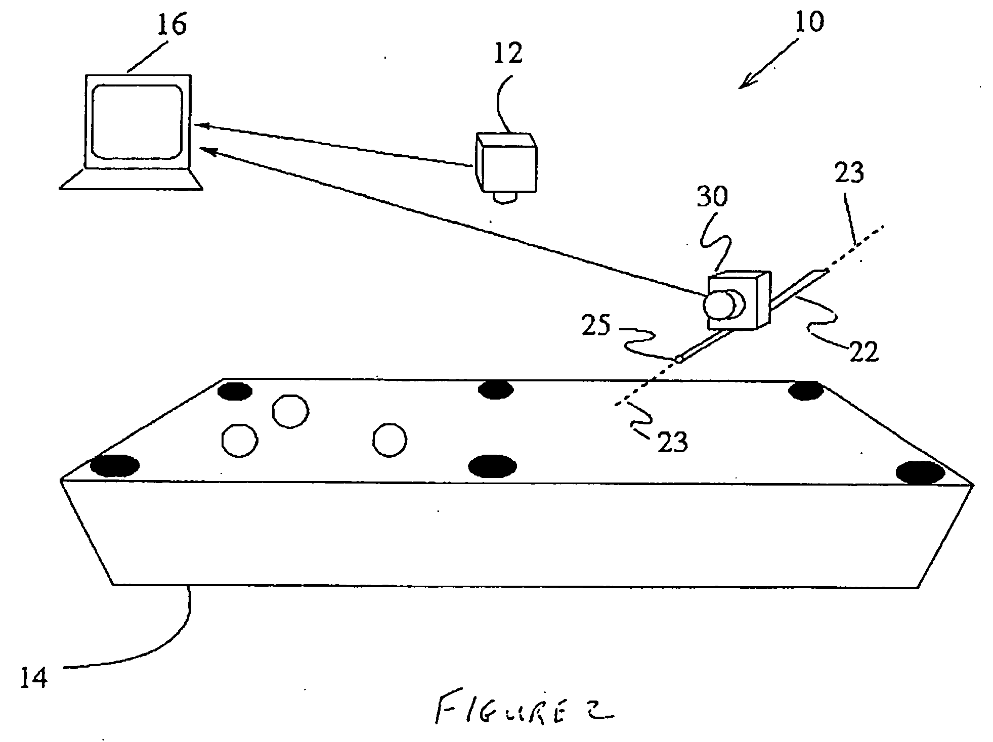
[0038] The apparatus and method of the present invention utilizes at least one, or two machine vision systems. Illustrations of the system are shown generally at 10 in FIGS. 1 and 2.

[0039] In one embodiment of the invention a single, global overhead camera is used. In this embodiment the system 10 uses global overhead camera 12 for acquiring an image of pool table 14 with camera 12 being placed above the pool table 14 and positioned such that its image plane is substantially parallel to both the pool table 14 and a longitudinal axis 23 of pool cue 22 and transmitting this image to a computer 16 for analysis, the result of which is a determination of the position and identity of each ball 18 on the pool table 14.

[0040] Another computer program is used to plan a shot, which indicates a desired position of the cue 22 with respect to the cue ball in the table frame. The gantry robot 26 mounted above the pool table 14 is controlled by a robotic controller 32 that communicates with a co...


PUM


Abstract

The present invention provides a method and apparatus for accurately positioning a robotic pool-playing device. The system comprises a computer controlled robotic positioning device, such as a gantry robot, that can position a cue over the pool table and place a shot. A global camera is mounted on the ceiling looking down at the table, and the acquired images are transmitted to the computer for analysis to determine the identity and locations of the balls within the table coordinate reference frame. The computer also automatically determines which ball to strike. An aspect of the invention is the use of a local camera, mounted on or near the robotic end-effector in a fixed relationship with the cue, to improve the positioning error of the robotic device prior to placing a shot. By comparing the ball locations perceived from the vantage of the local camera with the known ball locations determined from the global camera image, the invention can calculate the acquired robotic positioning error, which can then be corrected for prior to placing the shot.

Description

CROSS REFERENCE TO RELATED APPLICATION [0001] This patent application relates to, and claims the priority benefit from, U.S. Provisional Patent Application Ser. No. 60 / 612,247 filed on Sep. 23, 2004 entitled METHOD AND APPARATUS FOR POSITIONAL ERROR CORRECTION IN A ROBOTIC POOL SYSTEM USING A CUE-ALIGNED LOCAL CAMERA, and which is incorporated herein in its entirety.FIELD OF THE INVENTION [0002] This invention relates generally to the field of robotically controlled games, and more particularly the present invention relates to a method and apparatus for robotically controlled pool games. BACKGROUND OF THE INVENTION [0003] The cue sports include pool, billiards, and snooker, and have recently enjoyed a surge in popularity worldwide. There have been a number of efforts at developing automation aids for these games. One example is the Instant Pool Trainer [Lar01], in which a camera is mounted on the ceiling aimed down at the table. Acquired images are transmitted to a computer and auto...

Claims


Application Information

Patent Timeline
IPC IPC(8): A63D15/00
CPCB25J9/1697A63D15/00
Inventor GREENSPAN, MICHAEL
Owner GREENSPAN MICHAEL
Why Eureka
Try Eureka