Method for machining circular magnetic steel

A processing method, a ring-shaped technology, which is applied in the field of magnetic steel processing, can solve the problems of product performance, magnetization direction deviation, and deviation, etc., to improve smoothness, reduce angle deviation, and reduce magnetism. Effect of declination error

Active Publication Date: 2015-07-08
NINGBO YUNSHENG HIGH TECH MAGNETICS +4
View PDF4 Cites 0 Cited by
  • Summary
  • Abstract
  • Description
  • Claims
  • Application Information

AI Technical Summary

Problems solved by technology

In the above method, due to the deviation when confirming the magnetization direction through the magnetic field, there will be deviation when marking the line manually, and the width of the marking line will also cause positioning deviation. The combination of the above deviations will lead to the drilling position of the two countersink holes There is a large deviation (the deviation is ±15 degrees), which leads to a large deviation in the magnetization direction of the circular ring magnet determined according to the two countersink holes during the application process, and the accuracy is low; It needs to be demagnetized before entering the next process, and the product demagnetization process is likely to cause defects such as product missing corners and product performance changes

Method used


Image

  • Method for machining circular magnetic steel
  • Method for machining circular magnetic steel
  • Method for machining circular magnetic steel

Examples


Embodiment 1

[0027] Embodiment one: a kind of processing method of circular magnetic steel, it is characterized in that comprising the following steps:

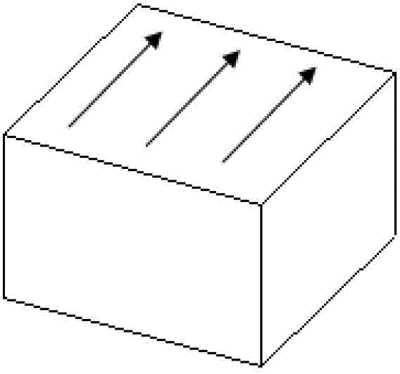
[0028] (1) Take a magnetic steel billet;

[0029] (2) According to the technical indicators of the circular magnetic steel to be processed, set the machining allowance and the position marks corresponding to the two countersink holes to be processed in the cutting equipment;

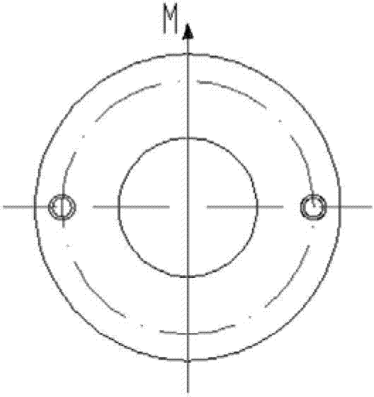
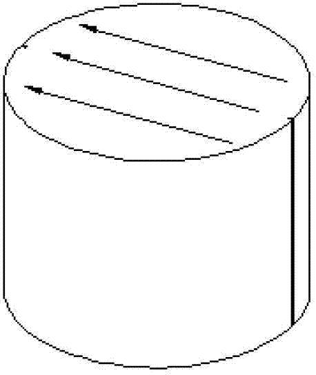
[0030] (3) Install the magnetic steel blank in the cutting equipment, cut the magnetic steel blank to obtain a cylindrical magnetic steel with position marks corresponding to the two countersink holes to be processed, the centerline of the two position marks is consistent with the two position marks to be processed The center line of the counterbore is on the same plane;

[0031] (4) Process the inner hole of the cylindrical magnetic steel to obtain a semi-finished circular magnetic steel;

[0032] (5) Fix and install the semi-finished circular magnetic steel in t...

Embodiment 2

[0036] Embodiment 2: This embodiment is basically the same as Embodiment 1, the only difference is that the outer diameter machining allowance of the wire cutting equipment is set to 1 mm, and the depth of the groove is 0.5 mm. Compared with Embodiment 1, the present embodiment In the processing method, the machining allowance is large, the material waste is also large, and the product cost is high.

Embodiment 3

[0037] Embodiment three: a kind of processing method of circular magnetic steel, it is characterized in that comprising the following steps:

[0038] (1) Take a magnetic steel billet;

[0039] (2) According to the technical indicators of the circular magnetic steel to be processed, set the machining allowance and the position marks corresponding to the two countersink holes to be processed in the cutting equipment;

[0040] (3) Install the magnetic steel blank in the cutting equipment, cut the magnetic steel blank to obtain a cylindrical magnetic steel with position marks corresponding to the two countersink holes to be processed, the centerline of the two position marks is consistent with the two position marks to be processed The center line of the counterbore is on the same plane;

[0041] (4) Process the inner hole of the cylindrical magnetic steel to obtain a semi-finished circular magnetic steel;

[0042] (5) Fix and install the semi-finished circular magnetic steel in...


PUM

PropertyMeasurementUnit
depthaaaaaaaaaa
depthaaaaaaaaaa
depthaaaaaaaaaa

Abstract

The invention discloses a method for machining circular magnetic steel. The method includes steps of taking a magnetic steel blank; setting machining allowance of cutting equipment and marking position marks corresponding to countersunk holes to be machined; mounting the magnetic steel blank in the cutting equipment, and cutting the magnetic steel blank to obtain cylindrical magnetic steel with position marks corresponding to the two countersunk holes to be machined; machining an inner hole of the cylindrical magnetic steel to obtain a semi-finished circular magnetic steel product; fixedly mounting the semi-finished circular magnetic steel product in a perforating fixture properly so that the two position marks are aligned with positioning marks of the perforating fixture; mounting the perforating fixture on a workbench of a drilling machine, and starting the drilling machine to drill the two countersunk holes at corresponding positions on the semi-finished circular magnetic steel product; and precisely machining the outer surface of the semi-finished circular magnetic steel product after the holes are drilled so as to obtain the circular magnetic steel meeting requirements. The method has the advantages that deviation of an included angle between a center connecting line of the two countersunk holes and a magnetization direction of a product is reduced, precision of the magnetization direction is improved, and the qualified rate of the product is high.

Description

technical field [0001] The invention relates to a processing method of magnetic steel, in particular to a processing method of circular magnetic steel. Background technique [0002] At present, in order to identify the magnetization direction of the ring-shaped magnet, generally a counterbore is provided at two symmetrical positions on the ring-shaped magnet, such as figure 1 shown. The included angle between the line connecting the centers of the two counterbore holes and the magnetization direction of the ring-shaped magnetic steel is determined according to the requirements of the product, and the included angle is a known definite value. In the existing processing method of circular magnets, the cylindrical magnets are generally obtained first (the diameter is within the tolerance range required by the product), and then the cylindrical magnets are put into the magnetic field to confirm the magnetization direction. The magnetization direction and the angle between the ...

Claims


Application Information

Patent Timeline
Patent Type & Authority Patents(China)
IPC IPC(8): B23P13/02
Inventor 赵德荣钱定权李世杰
Owner NINGBO YUNSHENG HIGH TECH MAGNETICS
Why Eureka
Try Eureka