Fluid having recyclable viscosity

Active Publication Date: 2006-03-23
SCHLUMBERGER TECH CORP
View PDF6 Cites 42 Cited by
  • Summary
  • Abstract
  • Description
  • Claims
  • Application Information

AI Technical Summary

Benefits of technology

[0004] Yet another embodiment is an oilfield treatment method involving repeatedly cycling the viscosity of an oilfield treatment fluid between high viscosity and low viscosity, for example by cycling the pH. One more embodiment is a method of alternating the viscosity of an aqueous viscoelastic surfactant system containing an anionic surfactant, between a first viscosity greater than about 50 cP and a second viscosity less than about 50 cP by combining the components in an aqueous fluid and alternating the pH between a first value above about 5 and a second value below about 4, for example the pH is alternated between a first value above about 7 and a second value below about 4. The aqueous viscoelastic surfactant system may optionally contain a zwitterionic surfactant.
[0005] Another embodiment is a method of cleaning particles from a wellbore involving a) injecting into the wellbore an aqueous fluid having a viscosity sufficient to entrain the particles b) moving the aqueous fluid within the wellbore such that the fluid entrains the particles, c) bringing the fluid to the surface, d) and reducing the viscosity of the fluid such that the particles settle from the fluid and e) allowing the particles to settle from the fluid. In a further embodiment the viscosity of the fluid is then increased to a viscosity sufficient to entrain particles and steps a) through e) are repeated. In one embodiment the viscosity is changed by decreasing or increasing the pH. The fluid is optionally injected through a jetting tool. The fluid is optionally injected first into the portion of the region of the wellbore to be cleaned farthest from the surface, or optionally first into the portion of the region of the wellbore to be cleaned nearest to the surface.
[0006] Another embodiment is a method of cleaning particles from a we

Problems solved by technology

Such materials hinder or prevent operations.
Sand accumulated in production tubing in a wellbore at the start of or during production can greatly hinder production.
Some crosslinked po

Method used


Image

  • Fluid having recyclable viscosity
  • Fluid having recyclable viscosity
  • Fluid having recyclable viscosity

Examples


Example

EXAMPLE 1

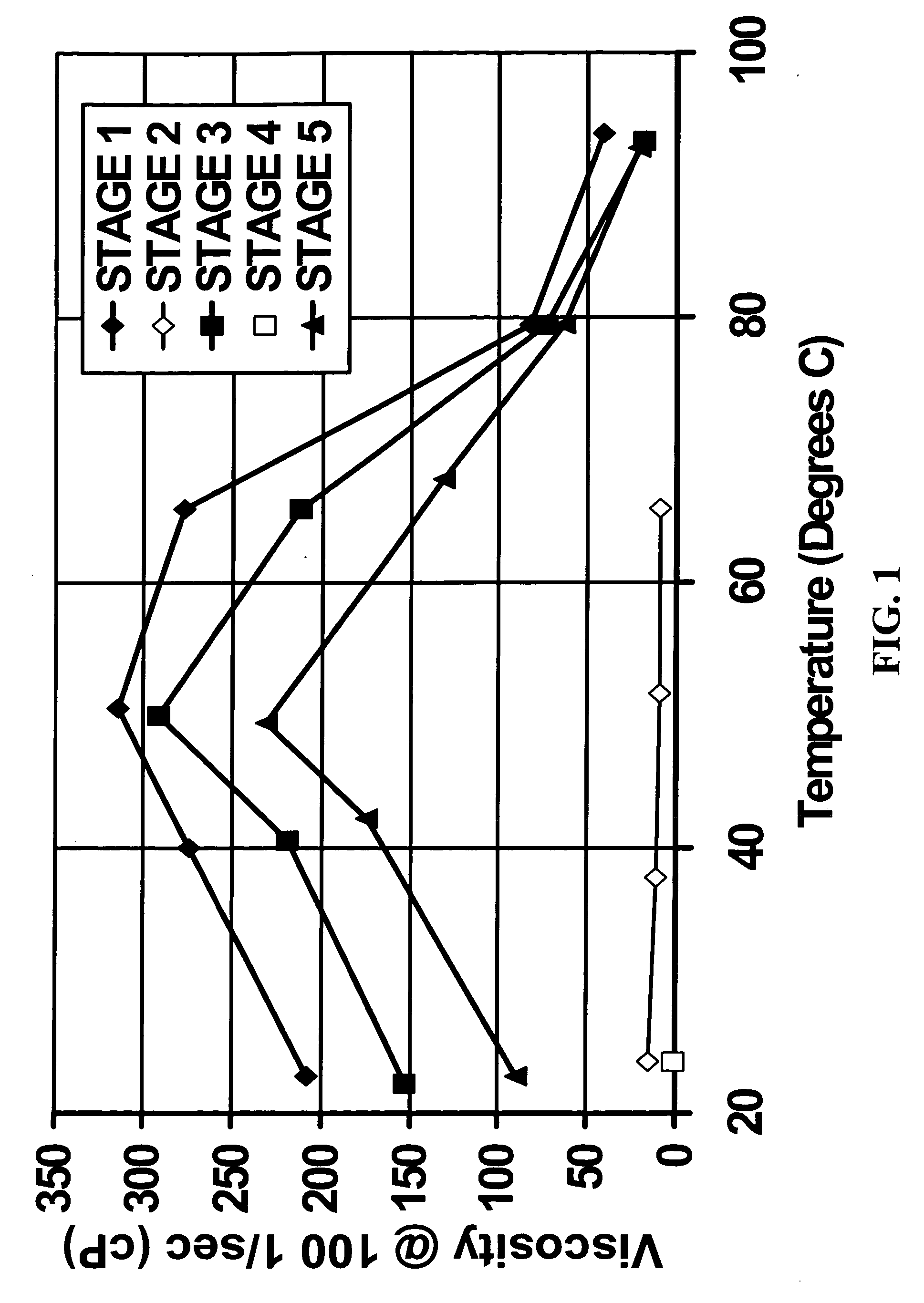
[0046] A 100 ml solution was made up in water with 4% oleic acid, 5% KCl, 0.4% EDTA and 2.5% of 30 wt % NaOH. The fluid had a pH of 12.62 and was a viscoelastic gel. The viscosity of this fluid as a function of temperature is shown in FIG. 1 as “Stage 1”. The fluid was then cooled and 0.75 ml of 37 wt % HCl was added; the fluid had a pH of 9.39 and very low viscosity, which is shown in FIG. 1 as “Stage 2”. The fluid was then cooled and 0.90 ml of 30 wt % NaOH was added; the fluid had a pH of 12.55 and was once again a viscous gel, which is shown in FIG. 1 as “Stage 3”. The fluid was then cooled and 0.75 ml of 37 wt % HCl was added; the fluid had a pH of 9.07 and very low viscosity, which is shown in FIG. 1 as “Stage 4”. The fluid was then cooled and 0.90 ml of 30 wt % NaOH was added; the fluid had a pH of 12.57 and was once again a viscous gel, which is shown in FIG. 1 as “Stage 5”. It is apparent that the fluid was repeatedly cycled between a fluid that could transport we...

Example

EXAMPLE 2

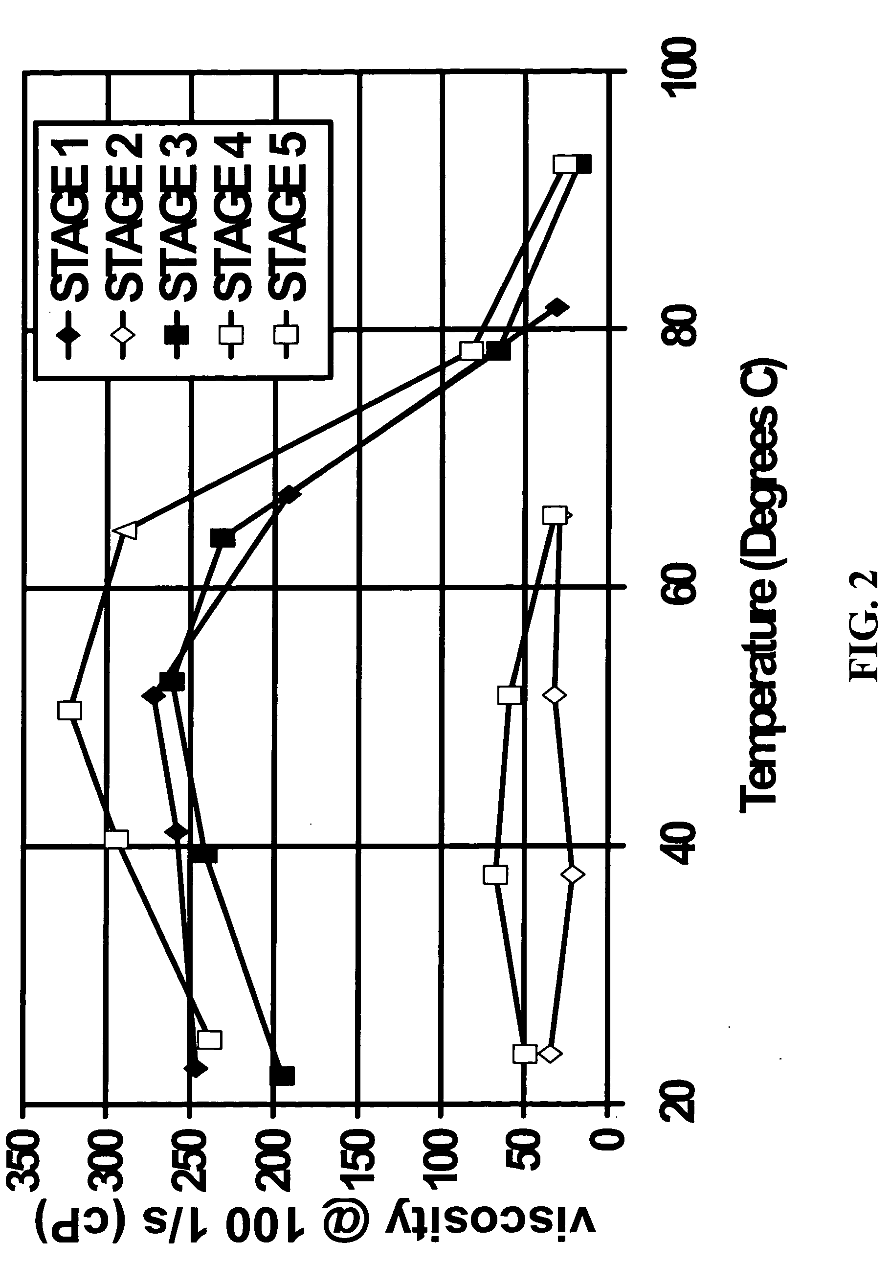
[0047] A 100 ml solution was made up in water with 4% oleic acid, 5% KCl, 0.4% EDTA and 2% of 45 wt % KOH. The fluid had a pH of 12.61 and was a viscoelastic gel. The viscosity of this fluid as a function of temperature is shown in FIG. 2 as “Stage 1”. The fluid was then cooled and 0.65 ml of 37 wt % HCl was added; the fluid had a pH of 9.35 and very low viscosity, which is shown in FIG. 2 as “Stage 2”. The fluid was then cooled and 0.85 ml of 45 wt % KOH was added; the fluid had a pH of 12.76 and was once again a viscous gel, which is shown in FIG. 2 as “Stage 3”. The fluid was then cooled and 0.65 ml of 37 wt % HCl was added; the fluid had a pH of 9.46 and very low viscosity, which is shown in FIG. 2 as “Stage 4”. The fluid was then cooled and 0.85 ml of 45 wt % KOH was added; the fluid had a pH of 12.78 and was once again a viscous gel, which is shown in FIG. 2 as “Stage 5”. It is apparent that the fluid was repeatedly cycled between a fluid that could transport wellbor...

Example

EXAMPLES 3 AND 4

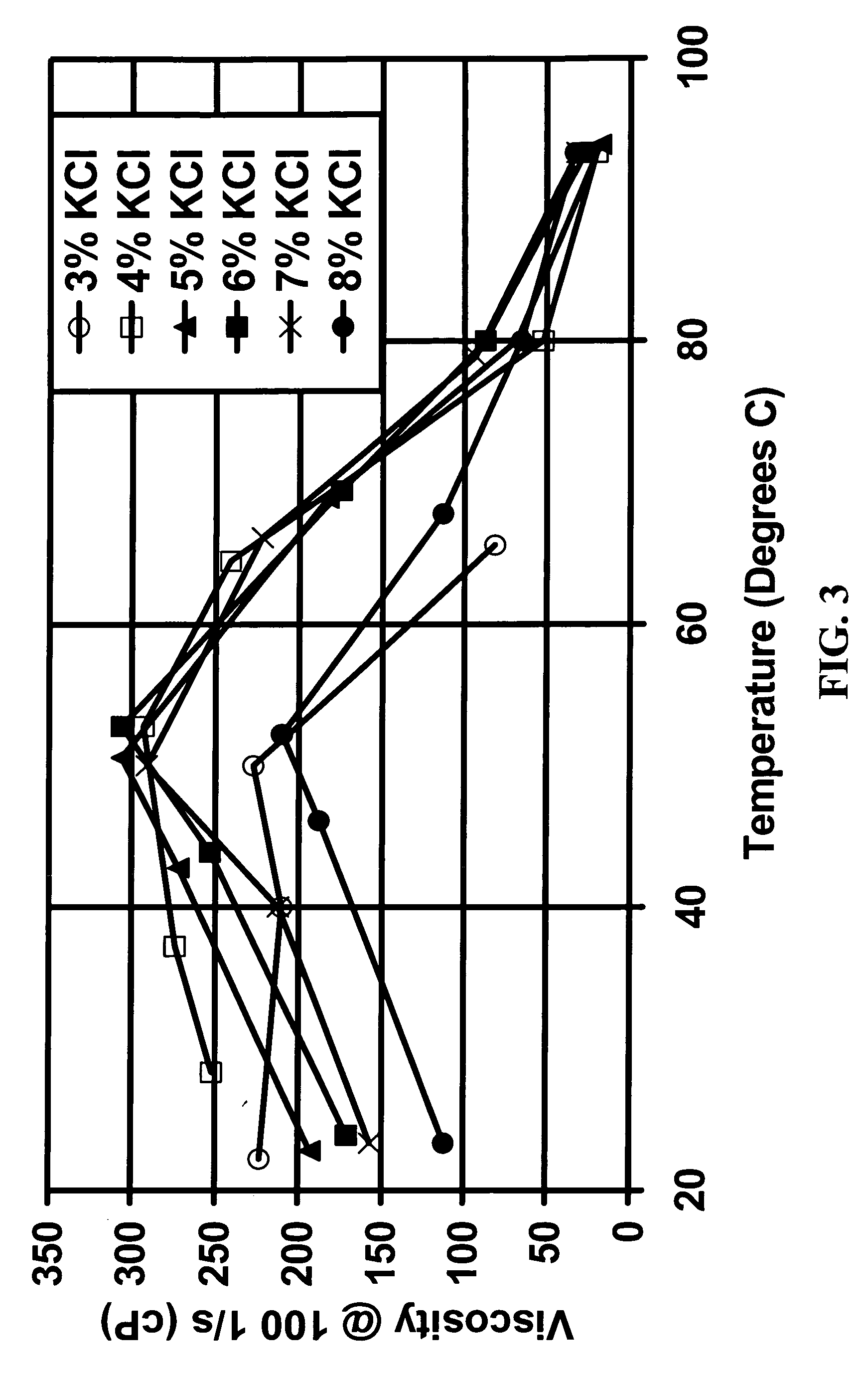
[0048] Two sets of fluids were prepared. In the first set, the fluid was made up in water with 4% oleic acid, 0.4% EDTA, 2.5% of 30 wt % NaOH, and varying amounts (3%, 4%, 5%, 6%, 7%, and 8%) of KCl. The viscosity as a function of temperature of these fluids is shown in FIG. 3. In the second set, the fluid was made up in water with 4% oleic acid, 0.4% EDTA, 2% of 45 wt % KOH, and varying amounts (3%, 4%, 5%, 6%, 7%, and 8%) of KCl. The viscosity as a function of temperature of these fluids is shown in FIG. 4. It can be seen that there is an optimal KCl concentration and useful concentration range for each fluid and that the effect of an increase in KCl depends somewhat on whether there was initially any Na ion present. Simple experiments of this type should be used to optimize the compositions and methods of the invention as a function of the choice and concentrations of surfactant, salt, acid, and base to be used.


PUM


Abstract

Compositions are given that have high viscosities at one pH range and low viscosities at another pH range. Methods are given for using such compositions in oilfield treatments. In particular CT wellbore cleanout compositions and methods are given in which a viscous fluid is injected into a wellbore; the fluid entrains particles and carries them to the surface; the viscosity of the fluid is reduced by reducing or increasing the pH; the particles settle from the fluid; the viscosity of the fluid is increased by increasing or reducing the pH; and the fluid is re-injected into the wellbore. Suitable surfactants are anionic surfactants, or mixtures of surfactants containing anionic surfactants, that aggregate into three-dimensional structures that substantially increase the viscosity at high pH but not at low pH. Other suitable surfactants are cationic surfactants with co-surfactants that aggregate below a certain pH but not above.

Description

BACKGROUND OF THE INVENTION [0001] This invention relates to fluids having recyclable viscosity and their use in oilfield treatments. More particularly, it relates to compositions and methods for cleaning debris from wellbores and wellbore tubing. Even more particularly it relates to removal of drill cuttings and other contaminants from a wellbore before or after cementing or completion and to removal of particulates after stimulation and / or during production. Most particularly, it relates to methods and compositions for recycling a fluid used in such cleanout operations. [0002] Material that has accumulated in a wellbore before or during completion is often called wellbore fill; it may be sand, proppant, cement chunks, or other materials. Such materials hinder or prevent operations. Sand accumulated in production tubing in a wellbore at the start of or during production can greatly hinder production. Coiled tubing has been widely used as a means to clean out the wellbore or product...

Claims


Application Information

Patent Timeline
IPC IPC(8): E21B37/00E21B43/00
CPCC09K2208/30C09K8/52
Inventor CHRISTANTI, YENNYFU, DIANKUIZHOU, JIAN
Owner SCHLUMBERGER TECH CORP
Why Eureka
Try Eureka