Storage device and write access processing method for storage device

Inactive Publication Date: 2006-03-23
HITACHI LTD
View PDF2 Cites 40 Cited by
  • Summary
  • Abstract
  • Description
  • Claims
  • Application Information

AI Technical Summary

Benefits of technology

[0007] In a conventional storage device, it is possible to switch between a write-through method and an after-write method for the storage device as a whole, but it is not possible, for example

Problems solved by technology

In a conventional storage device, it is possible to switch between a write-through method and an after-write method for the storage device as a whole, but it is not possible, for example, to

Method used


Image

  • Storage device and write access processing method for storage device
  • Storage device and write access processing method for storage device
  • Storage device and write access processing method for storage device

Examples


first embodiment

1. First Embodiment

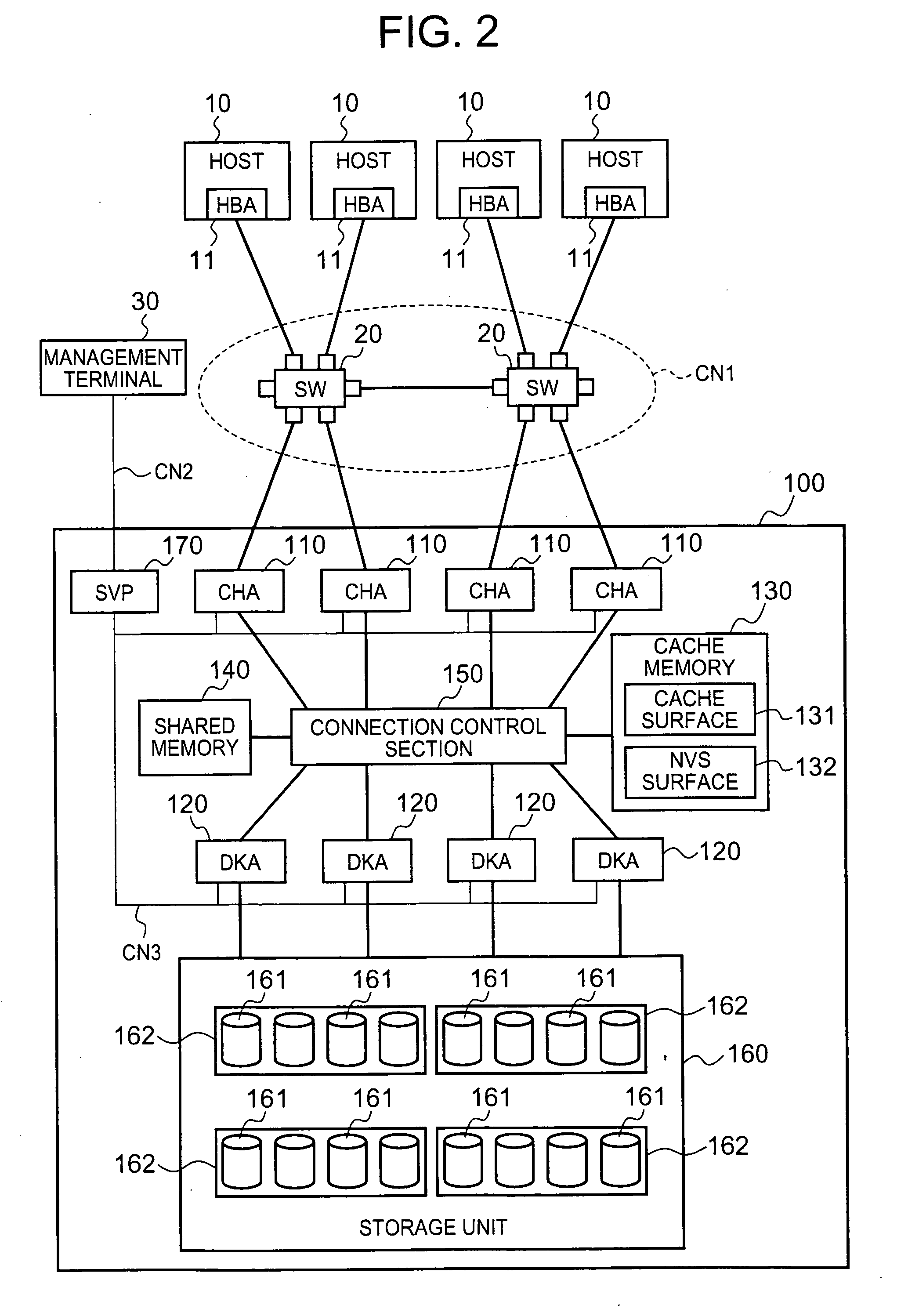
[0073]FIG. 2 is a block diagram of a storage system. This storage system may be constituted by comprising, for example, at least one or more host 10, at least one or more storage device 100, switches 20 for constituting a communications network between the host(s) 10 and the storage device 100, and a management terminal 30. As described hereinafter, the storage system may be constituted by comprising a plurality of storage devices 100 and 200.

[0074] Hosts 10 can be divided broadly into so-called open type host and mainframe type hosts, for example. Examples of an open type host include server machines which run a generic OS (Operating System), such as Windows (registered trademark), UNIX (registered trademark), or the like, and access the storage device 100 by means of a relatively generic communications protocol, such as FC (Fiber Channel), iSCSI (Internet SCSI), TCP / IP (Transmission Control Protocol / Internet Protocol), or the like. Examples of a mainframe type ...

second embodiment

2. Second Embodiment

[0141] A second embodiment of the present invention is now described on the basis of FIG. 15 to FIG. 17. The respective embodiments described below correspond to modifications of the first embodiment. The characteristic feature of this embodiment lies in the fact that when the processing mode is changed for any one LDEV of the plurality of LDEVs constituting one LU, the processing modes for the other LDEVs are also changed automatically.

[0142] As shown by the LDEV number conversion table T3 in FIG. 15, one LU “#0” is constituted by two LDEVs, LDEV “#0” and LDEV “#10”, for example. FIG. 16 is a flowchart showing a write-through flag setting process and correcting process. In the present embodiment, when the write-through flag of a prescribed LDEV is changed by means of the SVP 170, the write-through flags of the other LDEVs related to that LDEV are also changed automatically by the CHA 110.

[0143] The processing in S11-S15 has already been described and hence fur...

third embodiment

3. Third Embodiment

[0147]FIG. 18 is a flowchart showing a write-through flag setting process relating to a third embodiment of the present invention. In the present embodiment, the operations of setting and correcting the write-through flags are both executed by the SVP 170.

[0148] More specifically, a user logs in to the SVP 170 via the management terminal 30 (S131), calls up a parity group management screen (S132), and sets a write-through flag independently, for a desired LDEV (S133).

[0149] When the user has finished setting the write-through flag, the SVP 170 detects the LDEVs belonging to the same LU (S134), and examines whether or not the write-through flags of the group of mutually related LDEVs are matching (S135). If the write-through flags of the group of related LDEVs are not matching (S136: NO), then the SVP 170 harmonizes the write-through flags by means of a similar method to that described in the previous embodiment (S137). As stated in the first embodiment, the SVP ...


PUM


Abstract

The present invention allows the processing mode for write access operations to be set independently and respectively for prescribed units. The processing modes for handling write access are set previously for each of the volumes 6A and 6B. If the cache memory is functioning normally, write access operations to the respective volumes 6A and 6B are processed by means of an after-write method as illustrated in FIG. 1(a). If an abnormality has occurred in the cache memory, then write access operations to the volumes 6A and 6B are processed by means of a method previously selected from a write-through method as illustrated in FIG. 1(b) or a non-redundant storage type write-after method as illustrated in FIG. 1(c). By using different processing modes for write access, for each of the volumes 6A and 6B, it is possible to set a suitable processing mode respectively for each of the prescribed units, in accordance with the composition of the storage system, the operation configuration, and the like.

Description

CROSS-REFERENCE TO RELATED APPLICATIONS [0001] This application relates to and claims priority from Japanese Patent Application No. 2004-275101 filed on Sep. 22, 2004, the entire disclosure of which is incorporated herein by reference. BACKGROUND OF THE INVENTION [0002] The present invention relates to a storage device and a write access processing method for a storage device. [0003] This storage device provides a storage area based on a RAID (Redundant Arrays of Inexpensive Disks) system, wherein disk drives, such as hard disk drives, or the like, are arranged in an array configuration. A host computer (hereinafter, called “host”) accesses the logical storage area provided by the storage device and reads or writes data. [0004] The storage device stores write data received from the host, on the disk drives, via a cache memory. Furthermore, for example, if data requested by the host is not stored in the cache memory, then the storage device reads out the data requested by the host, f...

Claims


Application Information

Patent Timeline
IPC IPC(8): G06F12/00
CPCG06F3/0605G06F3/0622G06F3/065G06F2211/1009G06F11/1076G06F12/0804G06F12/0866G06F3/0689
Inventor KATSURAGI, EIJUFUKUOKA, MIKIO
Owner HITACHI LTD
Why Eureka
Try Eureka