Vapor-compression refrigerant cycle system with ejector

a technology of refrigerant cycle and ejector, which is applied in refrigeration components, transportation and packaging, light and heating equipment, etc., can solve the problems of lubrication oil shortage in the compressor, reduced lubrication oil return amount, etc., to prevent lubrication oil shortage, and improve the lubrication property of the compressor

Active Publication Date: 2006-03-30
DENSO CORP
View PDF4 Cites 11 Cited by
  • Summary
  • Abstract
  • Description
  • Claims
  • Application Information

AI Technical Summary

Benefits of technology

[0010] Alternatively, a check valve can be located at an inlet portion of the refrigerant suction port to only allow a refrigerant flow from the refrigerant suction pipe into the refrigerant suction port. Therefore, even when the refrigerant suction port is provided at a lower portion of the ejector, the check valve prevents the lubrication oil from flowing into the refrigerant suction pipe from the refrigerant suction port.
[0011] In the vapor-compression refrigerant cycle system, an auxiliary valve member can be arranged in a refrigerant passage through which refrigerant from the second evaporator is introduced to the refrigerant suction port of the compressor. In this case, the valve member is located at an inlet portion of the refrigerant suction port of the ejector, and the auxiliary valve member is opened when the valve member is closed, so that the refrigerant flowing out of the second evaporator flows into the suction side of the compressor. Accordingly, even when the refrigerant suction port is provided at a lower portion of the ejector, lubrication oil is prevented from staying in the refrigerant suction pipe by the valve member and the auxiliary valve member.
[0012] The second evaporator can be arranged to perform a cooling operation for cooling air, and a blower for blowing air to the second evaporator can be provided. In this case, the valve member is opened so that refrigerant always flows into the second evaporator when the compressor operates, and the blower is stopped when the cooling function of the second evaporator is stopped. Because the refrigerant always flows into the second evaporator, a refrigerant stream from the second evaporator to the refrigerant suction port of the ejector can be always formed, thereby preventing the lubrication oil from staying in the refrigerant suction pipe.
[0013] Alternatively, the valve member can be forcibly opened, when a predetermined time passes after the valve member is closed while the compressor operates. Therefore, it can prevent a shortage of the lubrication oil in the compressor.
[0014] Furthermore, when the cooling operation of the second evaporator is stopped when the compressor stats operating, the valve member is opened once for a predetermined time. Accordingly, even at a start time of the compressor, the lubrication oil staying in the second evaporator and the refrigerant suction pipe can be returned to the compressor, thereby preventing a shortage of the lubrication oil in the compressor.
[0015] In the vapor-compression refrigerant cycle system, a bypass passage, through which refrigerant from the refrigerant radiator flows into the refrigerant suction port while bypassing the second evaporator and the valve member, can be provided. In this case, an auxiliary valve member is located in the bypass passage for opening and closing the bypass passage, and the auxiliary valve member is opened when the valve member is closed while the compressor operates. Accordingly, when the refrigerant evaporating function (e.g., cooling function) of the second evaporator is stopped, it can prevent the lubrication oil from being insufficient in the compressor, and lubrication property of the compressor can be effectively improved.

Problems solved by technology

In this case, a returning amount of the lubrication oil returning to the compressor is reduced, and a lubrication oil shortage may be caused in the compressor.

Method used


Image

  • Vapor-compression refrigerant cycle system with ejector
  • Vapor-compression refrigerant cycle system with ejector
  • Vapor-compression refrigerant cycle system with ejector

Examples


first embodiment

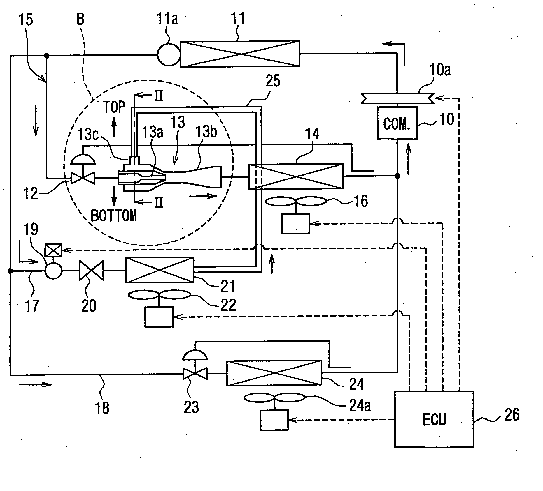
[0032] In the first embodiment, a vapor-compression refrigerant cycle system having an ejector, shown in FIG. 1, is typically used for a vehicle air conditioner, as an example. The vapor-compression refrigerant cycle system includes a main refrigerant path 15 in which refrigerant flows in this order of a discharge side of a compressor 10, a refrigerant radiator 11, a flow adjustment valve 12, an ejector 13, a first evaporator 14 and a suction side of the compressor 10.

[0033] In this embodiment, the compressor 10 for compressing refrigerant is driven and rotated by a vehicle engine through a belt and an electromagnetic clutch 10a, etc. The operation of the compressor 10 is switched and controlled by the electromagnetic clutch 10a. In this case, by controlling an on / off operation ratio of the compressor 10, a refrigerant discharge capacity of the compressor 10 can be controlled.

[0034] The refrigerant radiator 11 cools high-pressure refrigerant discharged from the compressor 10 by pe...

second embodiment

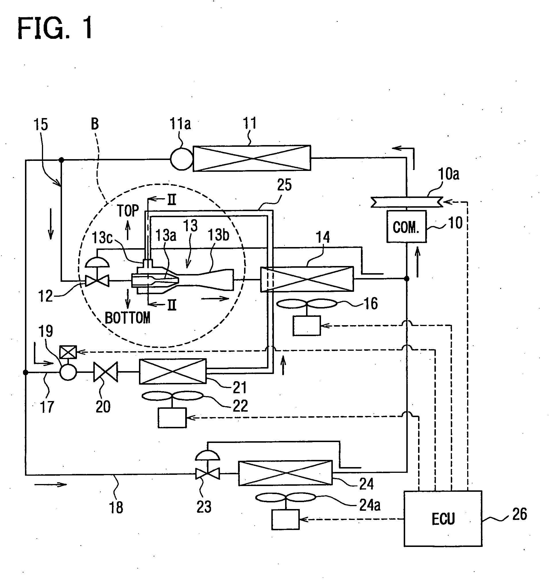
[0069] In the above-described first embodiment, the refrigerant suction port 13c of the ejector 13 is provided at an upper portion of the housing 13d. However, in the second embodiment, the refrigerant suction port 13c is provided at a lower portion of the housing 13d, and a standing portion 25a extending in a vertical direction is formed at a downstream portion in the refrigerant suction pipe 25, as shown in FIG. 4. The standing portion 25a can be vertically extended upwardly from a lowest portion of the ejector 13 by a predetermined height. In FIG. 4, H2 indicates the height of the standing portion 25a vertically extended.

[0070] In this embodiment, a downstream pipe portion downstream from the standing portion 25a in the refrigerant suction pipe 25 can be made shorter. Accordingly, even when the refrigerant suction portion 13c is arranged at the lower portion (e.g., bottom portion) of the housing 13d, the lubrication amount staying in the refrigerant suction pipe 25 can be contro...

third embodiment

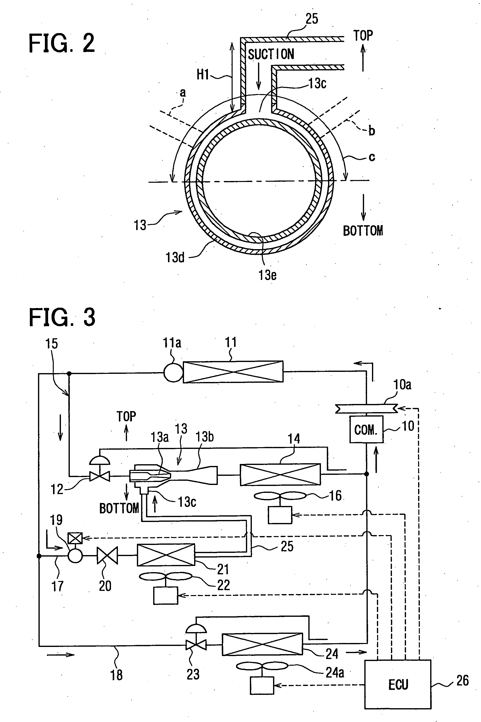
[0073]FIG. 5 shows a vapor-compression refrigerant cycle system of the third embodiment. In the third embodiment, the electromagnetic valve 19 is not provided in the first branch passage 17, and refrigerant flowing from the main refrigerant circulating path 15 flows into the second evaporator 21 in the first branch portion 17 after passing through the throttle mechanism 20. Therefore, when the compressor 10 is operated, refrigerant always flows into the second evaporator 21 in the first branch passage 17.

[0074] Thus, in this embodiment, when the refrigerator function (refrigerator cooling operation) is stopped, the operation of the second blower 22 is stopped. When the second blower 22 is stopped, a heat absorbing amount of the refrigerant in the second evaporator 2 is very small, and a large amount of the liquid refrigerant having passed through the throttle mechanism 20 is drawn into the refrigerant suction port of the ejector 13 without being evaporated in the second evaporator ...


PUM


Abstract

A vapor-compression refrigerant cycle system having an ejector includes a first evaporator for evaporating refrigerant from a pressure-increasing portion of the ejector, and a second evaporator for evaporating refrigerant to be drawn into a refrigerant suction port of the ejector. Furthermore, a valve member for opening and closing a refrigerant passage of the second evaporator is arranged in serious with the second evaporator in a refrigerant flow, and refrigerant flowing out of the second evaporator flows into the refrigerant suction port through a refrigerant suction pipe. The system is provided to restrict lubrication oil contained in refrigerant from being introduced from the ejector into and staying in the refrigerant suction pipe when the valve member is closed. For example, the refrigerant suction port is provided at an upper side of the ejector.

Description

CROSS REFERENCE TO RELATED APPLICATION [0001] This application is based on Japanese Patent Applications No. 2004-284098 filed on Sep. 29, 2004 and No. 2005-28165 filed on Feb. 3, 2005, the contents of which are incorporated herein by reference in its entirety. FIELD OF THE INVENTION [0002] The present invention relates to a vapor-compression refrigerant cycle system having an ejector used as a refrigerant decompression unit and a refrigerant circulating unit. The vapor-compression refrigerant cycle system is suitably used for a vehicle air conditioner, for example. BACKGROUND OF THE INVENTION [0003] A vapor-compression refrigerant cycle system (ejector cycle system) using an ejector as a refrigerant decompression unit and a refrigerant circulating unit is described in JP-B1-3322263 (corresponding to U.S. Pat. No. 6,574,987 and U.S. Pat. No. 6,477,857), for example. In this vapor-compression refrigerant cycle system, a first evaporator is arranged between the ejector and a gas-liquid...

Claims


Application Information

Patent Timeline
Patent Type & Authority Applications(United States)
IPC IPC(8): F25B43/02F25B1/06
CPCB60H1/323F25B5/02F25B31/004F25B41/00F25B2600/2519F25B2341/0011F25B2500/01F25B2500/16F25B2309/061
Inventor KOMATSU, HIROFUMIKOBAYASHI, SUTEOOSHITANI, HIROSHIKUSANO, KATSUYA
Owner DENSO CORP
Why Eureka
Try Eureka