Compressor

Inactive Publication Date: 2006-03-30
SANDEN CORP
View PDF48 Cites 32 Cited by
  • Summary
  • Abstract
  • Description
  • Claims
  • Application Information

AI Technical Summary

Benefits of technology

[0011] It is an object of the present invention to provide a compressor that allows a delivery port to be disposed in an

Problems solved by technology

The lubricating oil contained in the refrigerant, however, deteriorates the refrigeration performance of the refrigeration

Method used


Image

  • Compressor
  • Compressor
  • Compressor

Examples


Example

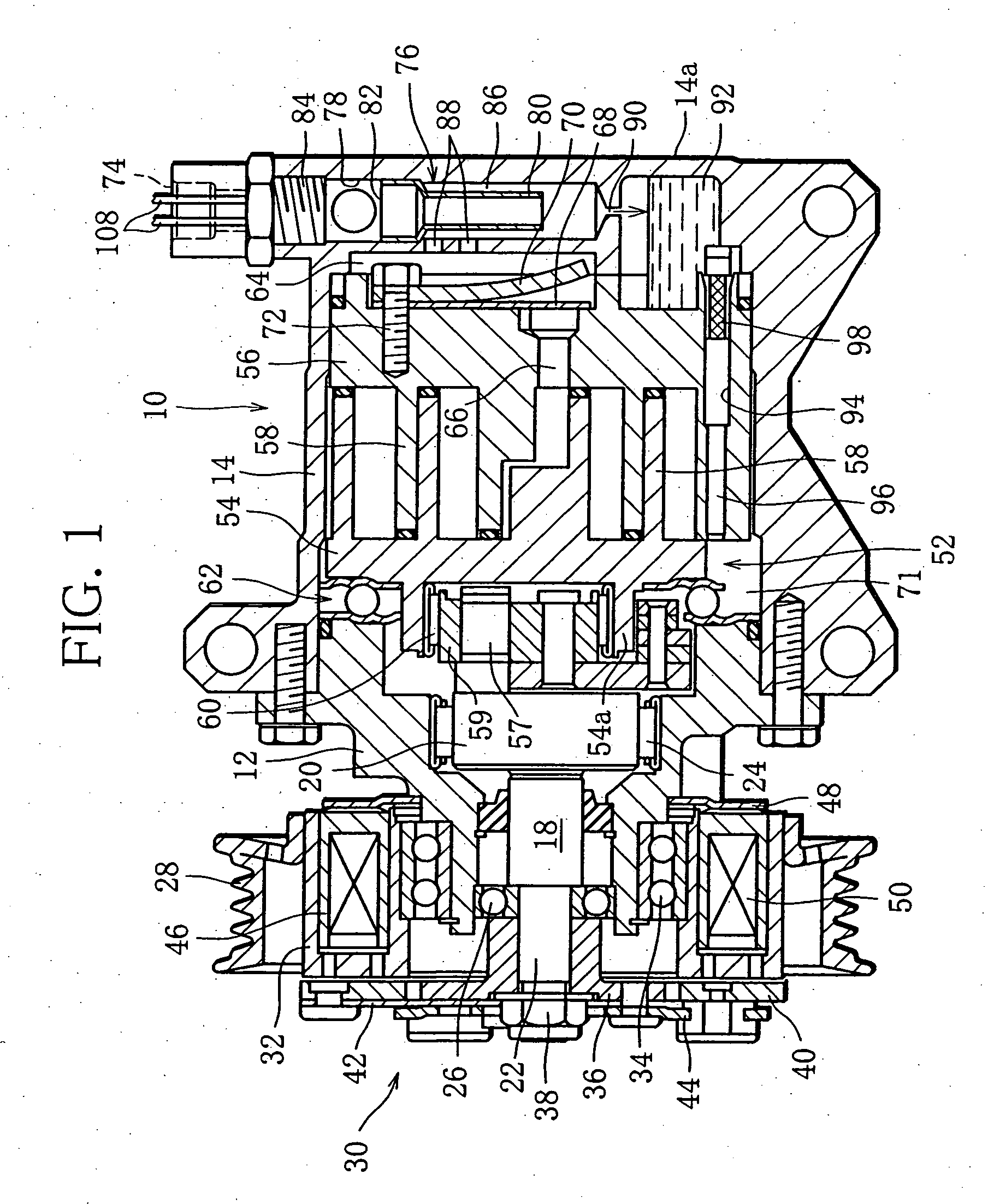
[0023] A scroll-type compressor shown in FIG. 1 is interposed in a refrigeration circuit of an air conditioning system for a vehicle and is used to compress a refrigerant in the refrigeration circuit. The refrigerant contains mist-like lubricating oil, which is used for lubrication of various moving parts and sliding parts disposed in the compressor.

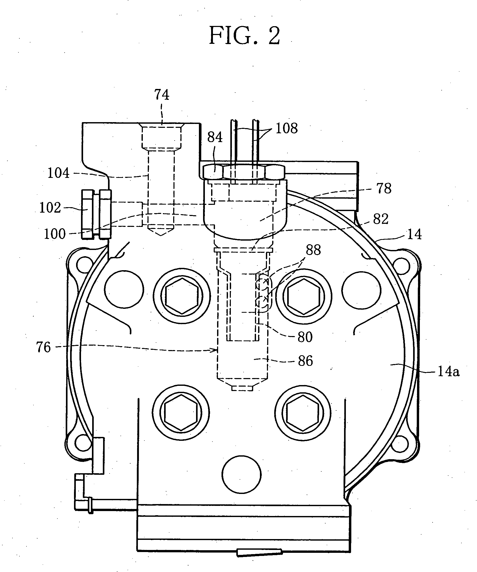
[0024] The compressor has a cylindrical housing 10. The housing 10 is provided with a front casing 12 and a rear casing 14. The casings 12 and 14 are coupled to each other with a plurality of coupling bolts 16.

[0025] Disposed in the front casing 12 is a drive shaft 18. The drive shaft 18 has a large diameter end 20 and a small diameter end portion 22. The large diameter end 20 is positioned on the rear casing 14 side, and is rotatably supported by the front casing 12 through a roller bearing 24. The small diameter end portion 22 is rotatably supported by the front casing 12 through a ball bearing 26, and outwardly projects from the fro...


PUM

PropertyMeasurementUnit
Sensitivityaaaaaaaaaa

Abstract

A compressor is provided with an oil separator for separating part of the lubricating oil contained in the compressed refrigerant, path arrangement for connecting a separation chamber of the separator and a delivery port of the compressed refrigerant, the path arrangement having a plurality of linear holes with opening ends that open in the outer surface of the housing wall, and screw plugs closing the opening ends except for the one serving as the delivery port, and a safety device built in at least one of the screw plugs, the safety device having a pressure relief valve and/or a temperature sensor.

Description

BACKGROUND OF THE INVENTION [0001] 1. Field of the Invention [0002] The present invention relates to a compressor for compressing a refrigerant in a refrigeration circuit included, for example, in an air conditioning system for a vehicle. [0003] 2. Description of the Related Art [0004] For instance, a compressor of this type is disclosed in Unexamined Japanese Patent Publication No. 2001-295767. The compressor disclosed in this publication includes a housing and a scroll-type compression unit that is accommodated in the housing. The compression unit sucks a refrigerant introduced into the housing to compress the refrigerant, and discharges a compressed refrigerant through a discharge hole into a discharge chamber defined in the housing. A high-pressure refrigerant in the discharge chamber is delivered from a delivery port of the housing toward a condenser disposed in a refrigeration circuit. [0005] In general, the refrigerant used in the refrigeration circuit contains lubricating oi...

Claims


Application Information

Patent Timeline
IPC IPC(8): F25B43/02
CPCF04B49/03F04C18/0215F04C28/26F04C28/28Y10S418/01F04C2270/18F04C2270/19F25B1/04F25B49/005F04C29/026
Inventor KUDO, TAKAYUKI
Owner SANDEN CORP
Why Eureka
Try Eureka