Directly operated pneumatic valve having a differential assist return

a pneumatic valve and differential assist technology, applied in the direction of valve housing, valve operating means/releasing devices, pressure relieving devices on sealing faces, etc., can solve problems such as unbalan

Active Publication Date: 2006-03-30
MAC VALVES INC
View PDF17 Cites 37 Cited by
  • Summary
  • Abstract
  • Description
  • Claims
  • Application Information

AI Technical Summary

Benefits of technology

[0006] A directly operated pneumatic valve having a differential assist return of the present invention provides a directly operated valve assembly which eliminates bypass flow ports. More specifically, the directly operated valve assembly includes a valve body having a pressurized air supply inlet port in communication with a source of pressurized air, and at least one cylinder port. A flow passage extends axially within the valve body, and a valve member is moveably supported within the flow passage between predetermined positions to selectively direct pressurized air from the inlet port through the cylinder port. An actuator is mounted to the valve body for directly moving the valve member in a first direction. A biasing member is oppositely disposed from the actuator and positioned between the valve member and the valve body.

Problems solved by technology

When the valve actuator is energized and the valve member moves from the closed position, pressure forces acting on the differing areas resulting from the different diameters of the valve member result in an unbalanced condition.
The unbalanced pressure forces plus the force of the compressed biasing device create a net return force to operatively move the valve member in a direction opposite the movement induced by the actuator when the actuator is de-energized.

Method used


Image

  • Directly operated pneumatic valve having a differential assist return
  • Directly operated pneumatic valve having a differential assist return
  • Directly operated pneumatic valve having a differential assist return

Examples


Embodiment Construction

[0020] The following description of the preferred embodiments is merely exemplary in nature and is in no way intended to limit the invention, its application, or uses.

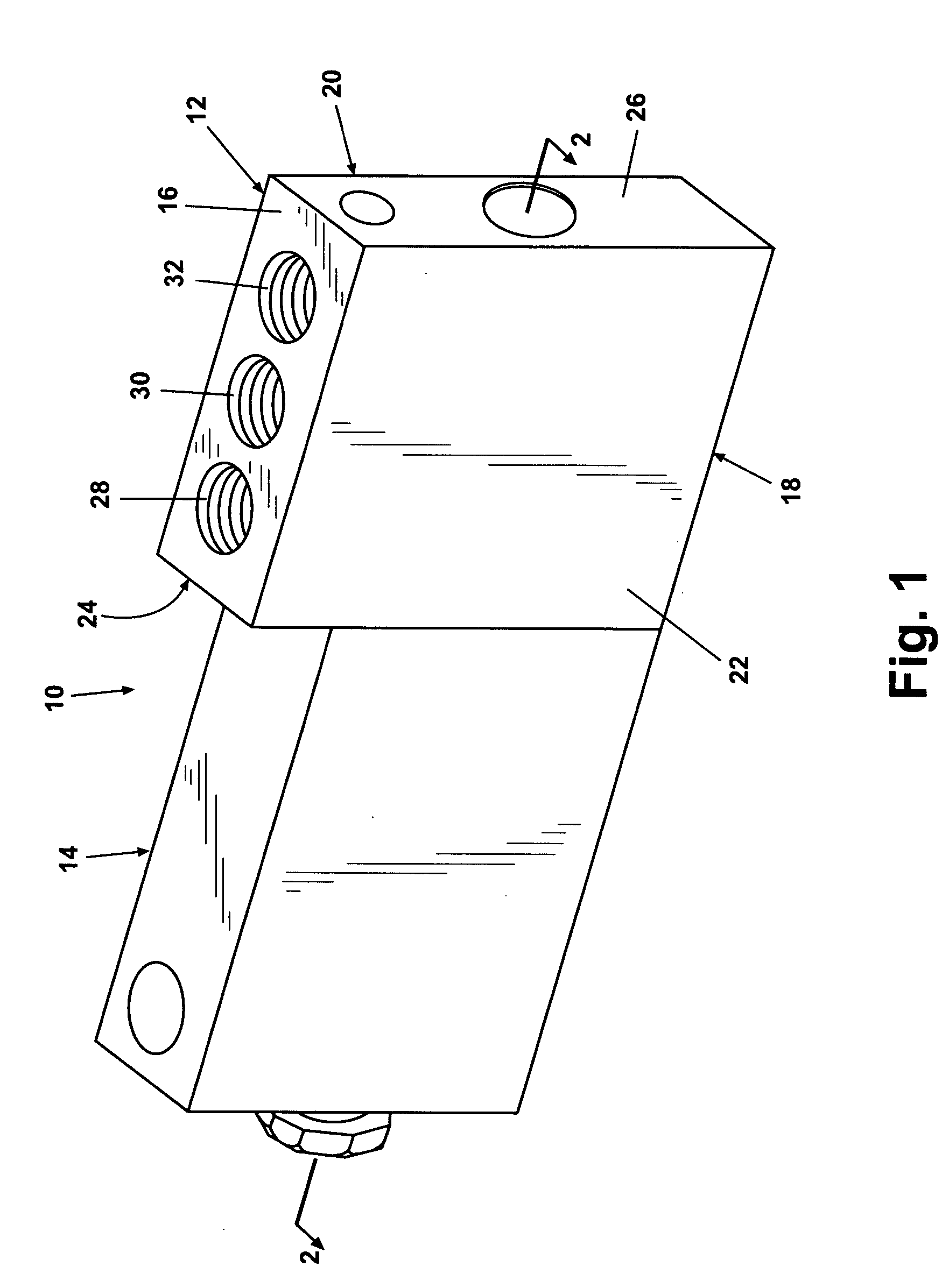
[0021] Referring now to the figures where like numerals are used to designate like structure throughout the drawings, one embodiment of a directly operated valve assembly of the present invention is generally indicated at 10 in FIG. 1. Valve assembly 10 includes a valve body 12 and an electromagnetic actuator 14 mounted to valve body 12. Valve body 12 has a thin rectangular shape defining top and bottom surfaces 16,18, respectively, a pair of opposed side surfaces 20,22 extending between the top and bottom surfaces 16 and 18, and end surfaces 24,26. In one preferred embodiment, actuator 14 is a solenoid assembly mounted to end surface 24 of valve body 12.

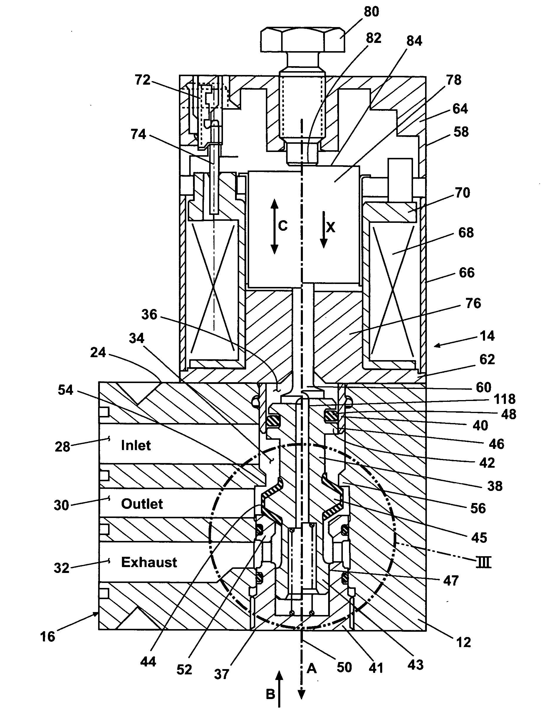
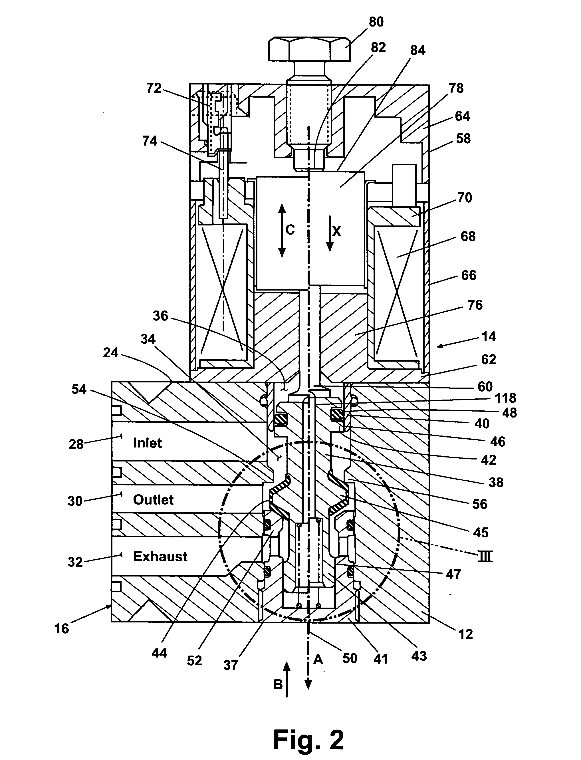
[0022] Referring now to FIGS. 2 and 3, valve body 12 includes a pressurized fluid inlet port 28 for communicating with a source of pressurized fluid (not shown), suc...


PUM


Abstract

A fluid control valve includes a valve body having both fluid inlet and discharge ports. A flow passage axially extending within the valve body communicates with the inlet and discharge ports. A valve member within the flow passage is movable by an actuator force in a first direction to direct a pressurized fluid from the inlet to the discharge port. The valve member includes first and second valve heads having different diameters and a valve seating member. The valve seating member engages first and second sealing diameters of the flow passage, the second sealing diameter being smaller than the first. Fluid pressure acting on the different diameters of the first valve head and valve seating member in contact with the second sealing diameter creates a net return force directing the valve member in a second direction opposite to the first direction upon removal of the actuator force.

Description

FIELD OF THE INVENTION [0001] The present invention relates in general to pneumatic valve assemblies and more specifically to a directly operated pneumatic valve. BACKGROUND OF THE INVENTION [0002] Directly operated, or actuated, pneumatic valves are well known in the art for controlling the flow of pressurized air therethrough. Directly operated valves may be used alone or in connection with, for example, spool valves and regulators that, in turn, control the flow of pressurized air to and from various pneumatically actuated devices such as press clutches, air brakes, sorting devices or any other pneumatic device or application requiring precise control of operating air. Two-way, three-way, four-way, and five-way direct operated valve assemblies are commonly employed in these environments. Such valves may include a valve body having a flow passage formed in the valve body. A valve member is supported within the flow passage and moveable from one position to another in direct respon...

Claims


Application Information

Patent Timeline
Patent Type & Authority Applications(United States)
IPC IPC(8): F15B13/044
CPCF16K11/044F16K27/0263F16K27/029F16K31/0693F16K31/0696F16K31/0627Y10T137/86622Y10T137/86686F15B21/00
Inventor NEFF, ROBERT H.JANSSEN, ERIC P.LONG, LYNN R.
Owner MAC VALVES INC
Why Eureka
Try Eureka