Level shift circuit having timing adjustment circuit for maintaining duty ratio

Inactive Publication Date: 2006-03-30
RICOH ELECTRONIC DEVICES CO LTD
View PDF2 Cites 174 Cited by
  • Summary
  • Abstract
  • Description
  • Claims
  • Application Information

AI Technical Summary

Benefits of technology

[0022] According to at least one embodiment of the present invention, any given one of the first and second level shift circuit units starts level shift operation when the other one of the first and second level shift circuit units stops level shift operation, and the timing adjustment circuit unit produces the binary output signals having the second voltage range by adjusting a pulse width thereof in response to the first level-shifted signal and the second level-shifted signal such that the pulse width

Problems solved by technology

Accordingly, the related-art level shift circuit has a problem (first problem) in that the duty cycle and phase differ between the input signals INA and INB and the output signals OUTA and OUTB.
The former design strategy results in the size of the level shift circuit 105

Method used


Image

  • Level shift circuit having timing adjustment circuit for maintaining duty ratio
  • Level shift circuit having timing adjustment circuit for maintaining duty ratio
  • Level shift circuit having timing adjustment circuit for maintaining duty ratio

Examples


Embodiment Construction

[0033] In the following, embodiments of the present invention will be described with reference to the accompanying drawings.

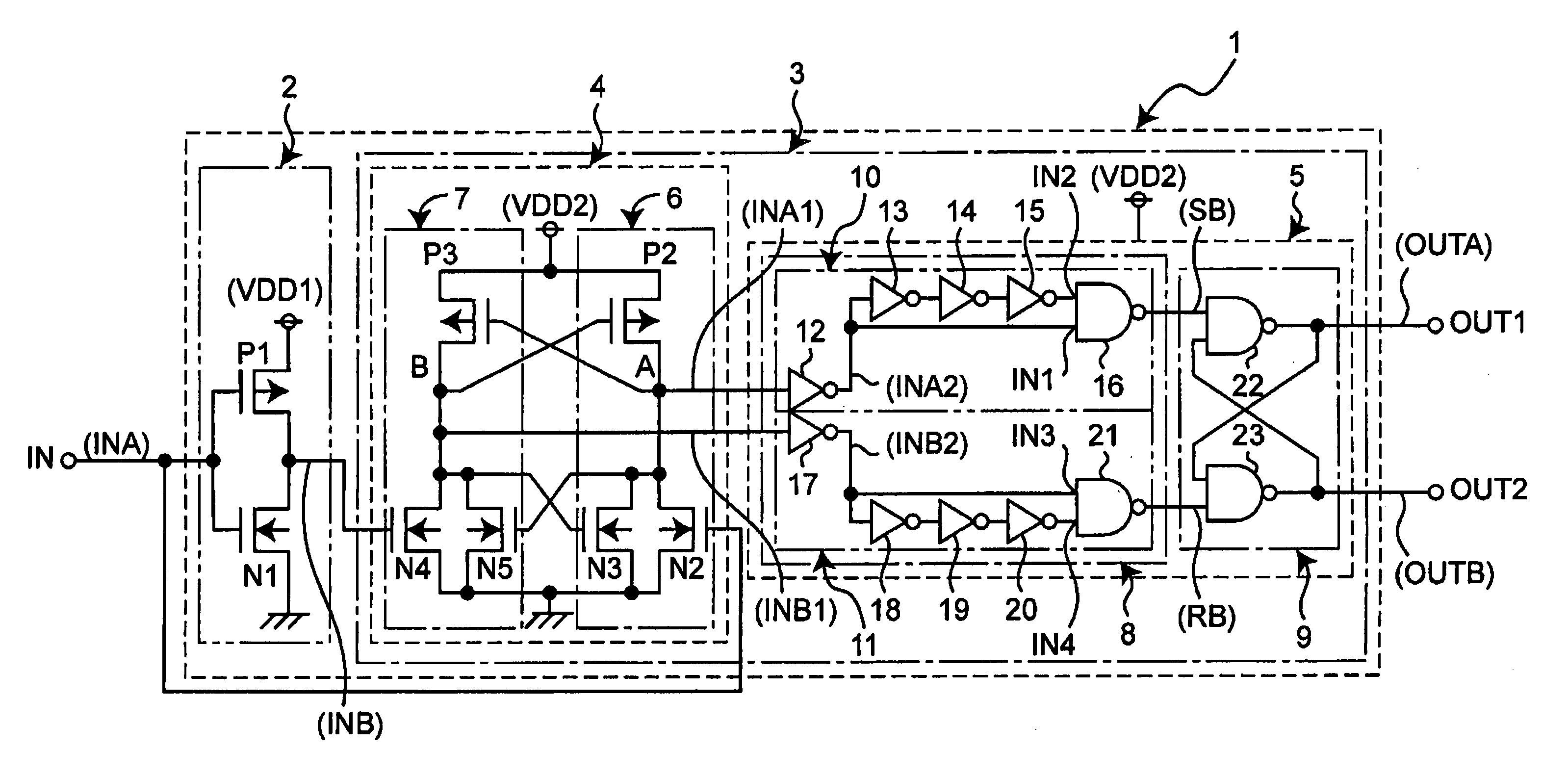
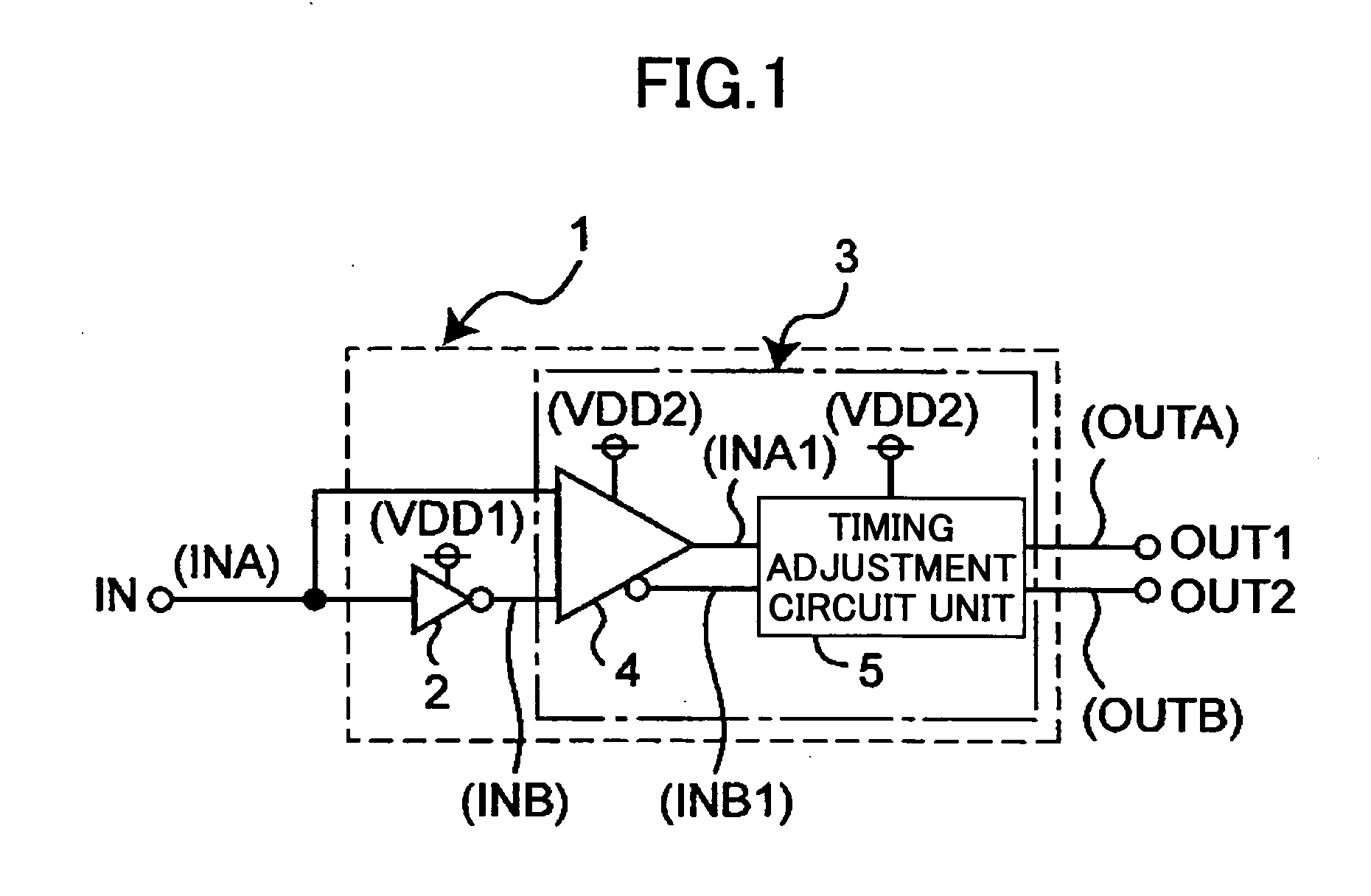
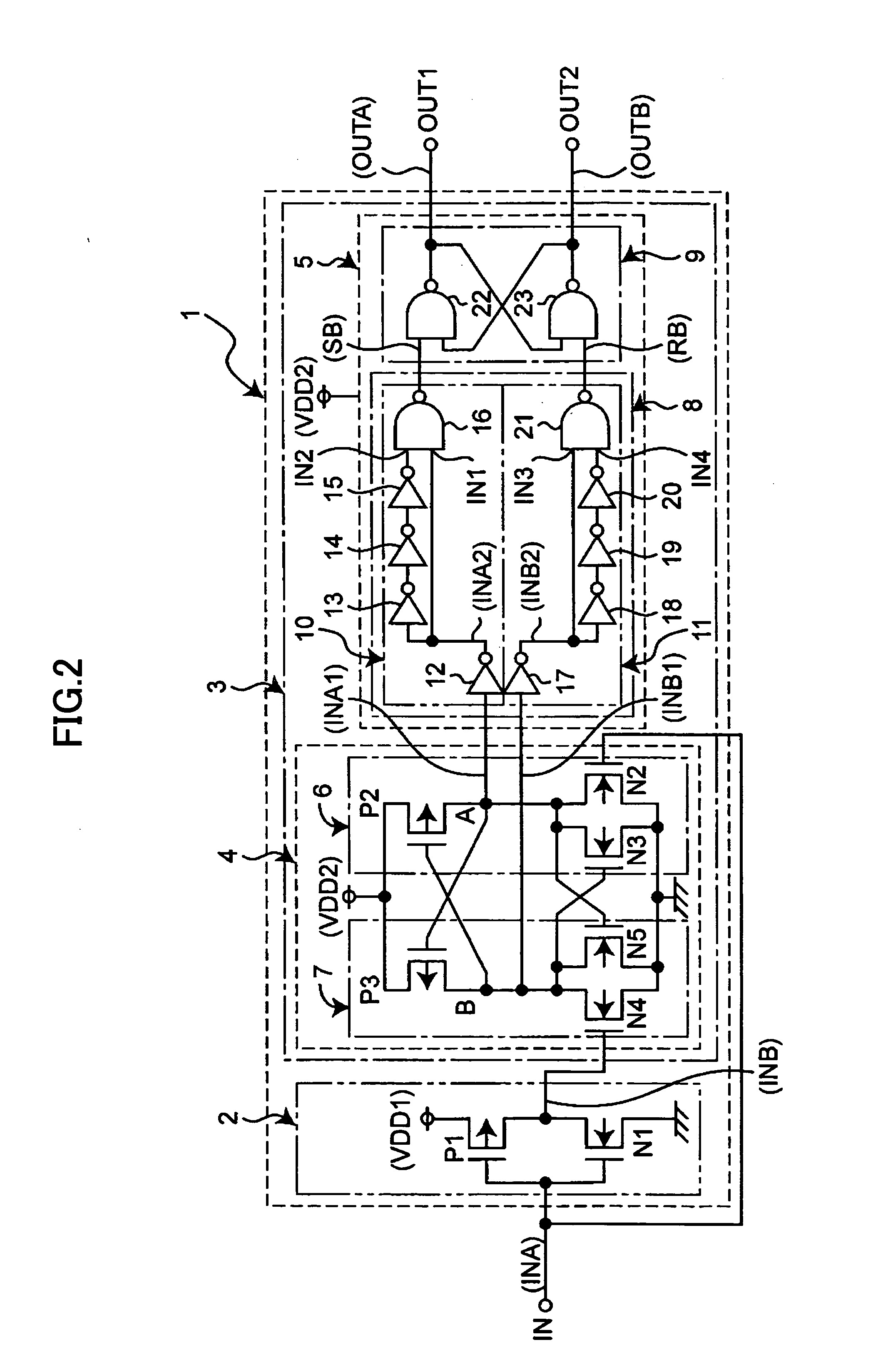
[0034]FIG. 1 is a circuit diagram showing an example of the configuration of a level shift apparatus including a level shift circuit according to the present invention. As shown in FIG. 1, a level shift apparatus 1 includes an inverter circuit 2 operating by use of a first predetermined positive-side power supply voltage VDD1 (e.g., 1.2 V) as a power supply, and also includes a level shift circuit 3 operating by use of a second predetermined positive-side power supply voltage VDD2 (e.g., 3.3 V) as a power supply where the second positive-side power supply voltage VDD2 is larger than the first positive-side power supply voltage VDD1. The level shift circuit 3 includes a level shift circuit unit 4 and a timing adjustment circuit unit 5. An input node IN of the inverter circuit 2 receives a signal INA output from an internal circuit (not shown) that operates by u...


PUM


Abstract

A level shift circuit for shifting levels of a pair of binary input signals having a first voltage range to produce a pair of binary output signals having a second voltage range includes a first circuit to shift a level of a first one of the binary input signals thereby to produce a first signal having the second voltage range, a second circuit to shift a level of a second one of the binary input signals thereby to produce a second signal having the second voltage range, and a timing adjustment circuit to produce the binary output signals by adjusting a pulse width thereof in response to the first and second signals such that the pulse width is equal to a time interval from when one of the first and second circuits stops level shift operation to when another one of the first and second circuits stops level shift operation.

Description

BACKGROUND OF THE INVENTION [0001] 1. Field of the Invention [0002] The present invention generally relates to level shift circuits, and particularly relates to a level shift circuit that receives a pair of input signals having two complementary levels with signal amplitudes ranging between a first predetermined positive-side power supply voltage and a predetermined negative-side power supply voltage, and produces a pair of output signals having two complementary levels by level-shifting the received signals to signals having amplitudes ranging between a second predetermined positive-side power supply voltage larger than the first predetermined positive-side power supply voltage and the predetermined negative-side power supply voltage [0003] 2. Description of the Related Art [0004]FIG. 6 is a circuit diagram showing an example of the configuration of a level shift apparatus including a related-art level shift circuit. [0005] The level shift apparatus 101 shown in FIG. 6 receives a s...

Claims


Application Information

Patent Timeline
IPC IPC(8): H03K19/0175
CPCH03K3/356113H03K3/017
Inventor MURAKAMI, HIDEAKI
Owner RICOH ELECTRONIC DEVICES CO LTD
Why Eureka
Try Eureka