
Plasma display apparatus

a technology of display apparatus and plasma, which is applied in the direction of electric discharge tubes, gas-filled discharge tubes, instruments, etc., can solve the problems of reducing the discharge voltage of discharge cells, pdp tending to produce erroneous discharge, and the output voltage control of such a power supply circuit cannot adequately suppress the degradation of image quality, etc., to achieve the effect of suppressing image degradation

Inactive Publication Date: 2006-03-30
PANASONIC CORP
View PDF13 Cites 18 Cited by
  • Summary
  • Abstract
  • Description
  • Claims
  • Application Information

AI Technical Summary

Benefits of technology

[0008] One object of the present invention is to provide a plasma display apparatus that can suppress image degradation caused by long-term usage.
[0009] Another object of the present invention is to provide a plasma display apparatus that can maintain favorable image quality even at low temperature, by suppressing erroneous discharge at low temperatures.

Problems solved by technology

Therefore, the discharge voltage of discharge cells decreases as a result of long-term usage and the PDP tends to produce erroneous discharge.
However, the output voltage control of such a power supply circuit cannot adequately suppress image quality degradation caused by long-term usage.
Further, there is another problem.
When the temperature of the environment in which the plasma display apparatus is used drops, the discharge cells of the PDP discharge erroneously and the display quality drops.
However, with such a method, a heater for uniformly heating the whole of the PDP must be mounted and the structure of the display apparatus becomes complicated.

Method used


Image

  • Plasma display apparatus
  • Plasma display apparatus
  • Plasma display apparatus

Examples


first embodiment

[0048] Referring to FIG. 1 to FIG. 16, a plasma display apparatus 49 according to a first embodiment of the present invention will be described.

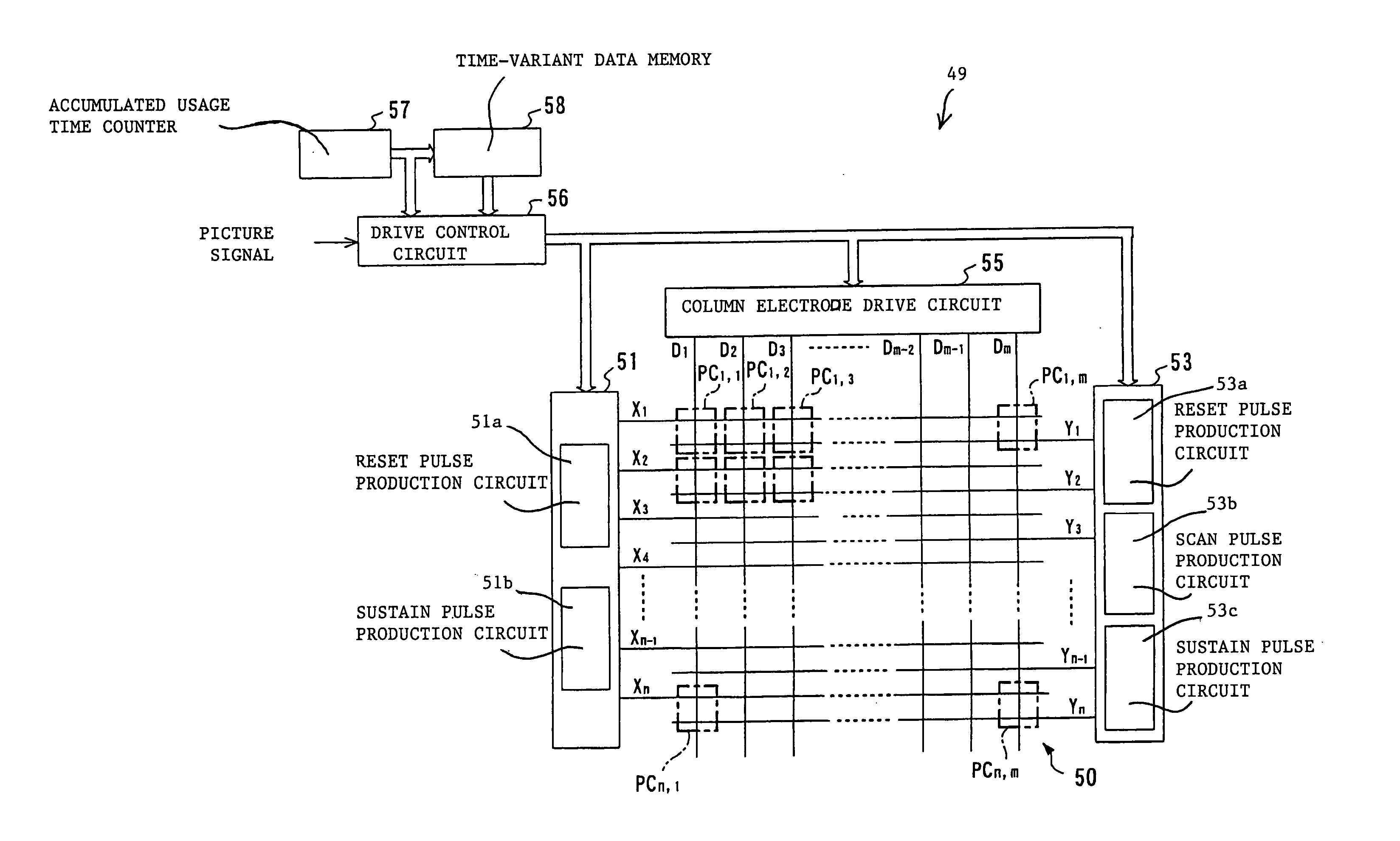
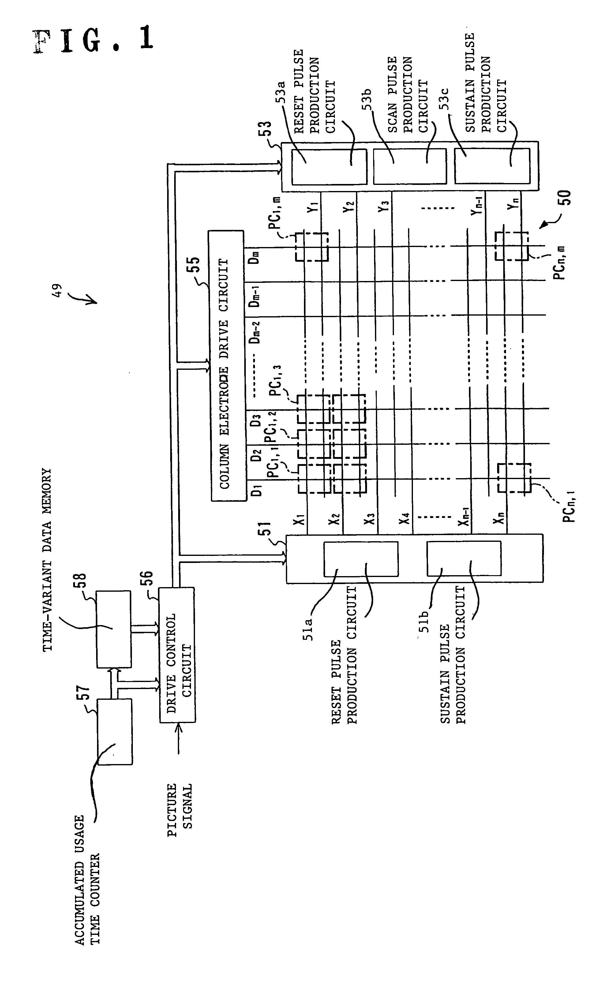
[0049] As shown in FIG. 1, the plasma display apparatus 49 includes a PDP (plasma display panel) 50, a row electrode X drive circuit 51, a row electrode Y drive circuit 53, a column electrode drive circuit 55, a drive control circuit 56, a usage time counter (timer) 57 and a time-variant data memory 58.

[0050] The PDP 50 has column electrodes D1 to Dm and row electrodes X1 to Xn and Y1 to Yn. The column electrodes D1 to Dm extend in the height direction (vertical direction) of a two-dimensional display screen of the PDP 50. The row electrodes X1 to Xn and row electrodes Y1 to Ym extend in the width direction (horizontal direction) of the display screen of the PDP 50. Each two adjacent row electrodes Xi and Yi define one row electrode pair. These row electrode pairs (X1, Y1), (X2, Y2), (X3, Y3), . . . , (Xn, Yn) define first to nth display l...

second embodiment

[0080] A second embodiment of the present invention will be described in detail hereinbelow with reference to FIGS. 17 to 29.

[0081]FIG. 17 shows a schematic constitution of the plasma display apparatus 49 of the second embodiment of the present invention. Similar reference numerals and symbols are assigned to similar elements in the first and second embodiments.

[0082] As shown in FIG. 17, the plasma display apparatus 49 includes a PDP 50, a row electrode X drive circuit 51, a row electrode Y drive circuit 53, a column electrode drive circuit 55, a drive control circuit 56, and a panel temperature sensor 60.

[0083] The PDP 50 has column electrodes D1 to Dm and row electrodes X1 to Xn and Y1 to Yn. The column electrodes D1 to Dm extend in the heighth direction (vertical direction) of a two-dimensional display screen of the PDP 50, and the row electrodes X1 to Xn and row electrodes Y1 to Yn extend in the width direction (horizontal direction) of the display screen. Each two adjacent ...


PUM


Abstract

A plasma display apparatus includes a plasma display panel. Pulse voltage values and / or pulse widths of a variety of drive pulses that are applied to the plasma display panel are adjusted in accordance with the accumulated usage time of the plasma display panel.

Description

BACKGROUND OF THE INVENTION [0001] 1. Field of the Invention [0002] The present invention relates to a plasma display apparatus having a plasma display panel. [0003] 2. Description of the Related Art [0004] Plasma display apparatuses having a plasma display panel (referred to as “PDP” hereinafter) are marketed as thin-type, large-screen display devices. In the PDP, discharge cells corresponding to pixels are arranged in a matrix shape. The PDP implements an image display by using the phenomenon of light emission in accordance with discharge that is induced in each of the discharge cells. Therefore, the discharge voltage of discharge cells decreases as a result of long-term usage and the PDP tends to produce erroneous discharge. To deal with this problem, some display apparatus control a discharge-sustaining voltage that is applied to the discharge cells in accordance with the PDP usage time. One of such apparatus is disclosed in Japanese Patent Application Kokai (Laid Open) No. 9-13...

Claims


Application Information

Patent Timeline
IPC IPC(8): G09G3/28G09G3/288G09G3/292G09G3/294G09G3/296G09G3/298H01J17/49
CPCG09G3/2037G09G3/2922G09G3/2948G09G3/296H01J11/40G09G2320/041G09G2320/043H01J11/12G09G3/2983H01J11/22
Inventor TOKUNAGA, TSUTOMUSATO, YOSHICHIKASAEGUSA, NOBUHIKO
Owner PANASONIC CORP
Learn More