Transmission method for OFDM-MIMO communication system

Inactive Publication Date: 2006-03-30
SAMSUNG ELECTRONICS CO LTD +1
View PDF5 Cites 105 Cited by
  • Summary
  • Abstract
  • Description
  • Claims
  • Application Information

AI Technical Summary

Benefits of technology

[0010] An object of the present invention is to substantially solve at least the above problems and/or disadvantages and to provide at least the advantages below. It is, therefore, an object of the present inve

Problems solved by technology

However, because the optimal multiplexing gain or diversity gain can be subject to change according to the given channel environment, application of a fixed MIMO technique in a time-varying environment does not always guarantee efficient channel utilization.
However, this technique is limited only to the OFDM system, and adjusts transmission parame

Method used


Image

  • Transmission method for OFDM-MIMO communication system
  • Transmission method for OFDM-MIMO communication system
  • Transmission method for OFDM-MIMO communication system

Examples


first embodiment

[0042] A detailed algorithm of a data transmission method according to the present invention is as follows.

[0043] 1) Initial bits for all of subcarriers k (k=1, 2, . . . , N), spatial substreams j (j=1, 2, . . . , G), and a multiplexing gain G (≦Mt) are set to bj,kG=0, and initial power for all of the subcarriers k (k=1, 2, . . . , N) and the multiplexing gain G is set to PkG=0.

[0044] 2) Noise variances ηj,k(G) for all of the subcarriers k (k=1, 2, . . . , N), the spatial substreams j (j=1, 2, . . . , G), and the multiplexing gain G are calculated.

[0045] 3) A power increment ΔPj,k(G) required to transmit one more bit is calculated by Equation (1).

ΔPj,k(G)=(SNRbj,k(G)+1−SNRbj,k(G))ηj,k(G)+Pk(G)−Pkgk  (1)

[0046] Herein, gk denotes a multiplexing gain for a kth subcarrier selected at a previous iteration. Step 3) is performed on all of the subcarriers, the spatial modes, and the spatial subchannels.

[0047] 4) Spatial subchannel indexes jk(G) for the subcarriers k and the multiplexin...

second embodiment

[0056]FIGS. 4A and 4B are resource graphs for a description of a data transmission method according to another embodiment of the present invention. That is, the present invention selects a spatial mode using a correlation between consecutive subcarriers in the frequency domain.

[0057] As shown in FIG. 4A, the second embodiment of the present invention groups subcarriers by the predetermined number of subcarriers in the frequency domain, and selects a spatial mode for the center subcarrier in each subcarrier group. This is based on the assumption that adjacent subcarriers are subject to less change, and the second embodiment groups the subcarriers, selects a representative spatial mode for one of the subcarriers in each subcarrier group, and applies the same spatial mode to the adjacent subcarriers in the same group, thereby contributing to a reduction in calculation complexity. It is preferable that the number of subcarriers constituting a group is set large at the initial stage in o...

third embodiment

[0060]FIG. 5 is a resource graph for a description of a data transmission method according to further another embodiment of the present invention. That is, the present invention uses SNR characteristics in the frequency domain for the spatial mode. As shown in FIG. 5, it can be noted that when a transmitter transmits data in a spatial mode with G=1 or G=2, a variation in received SNR is less and a variation in SNR of each spatial channel is large for the spatial mode with G=4.

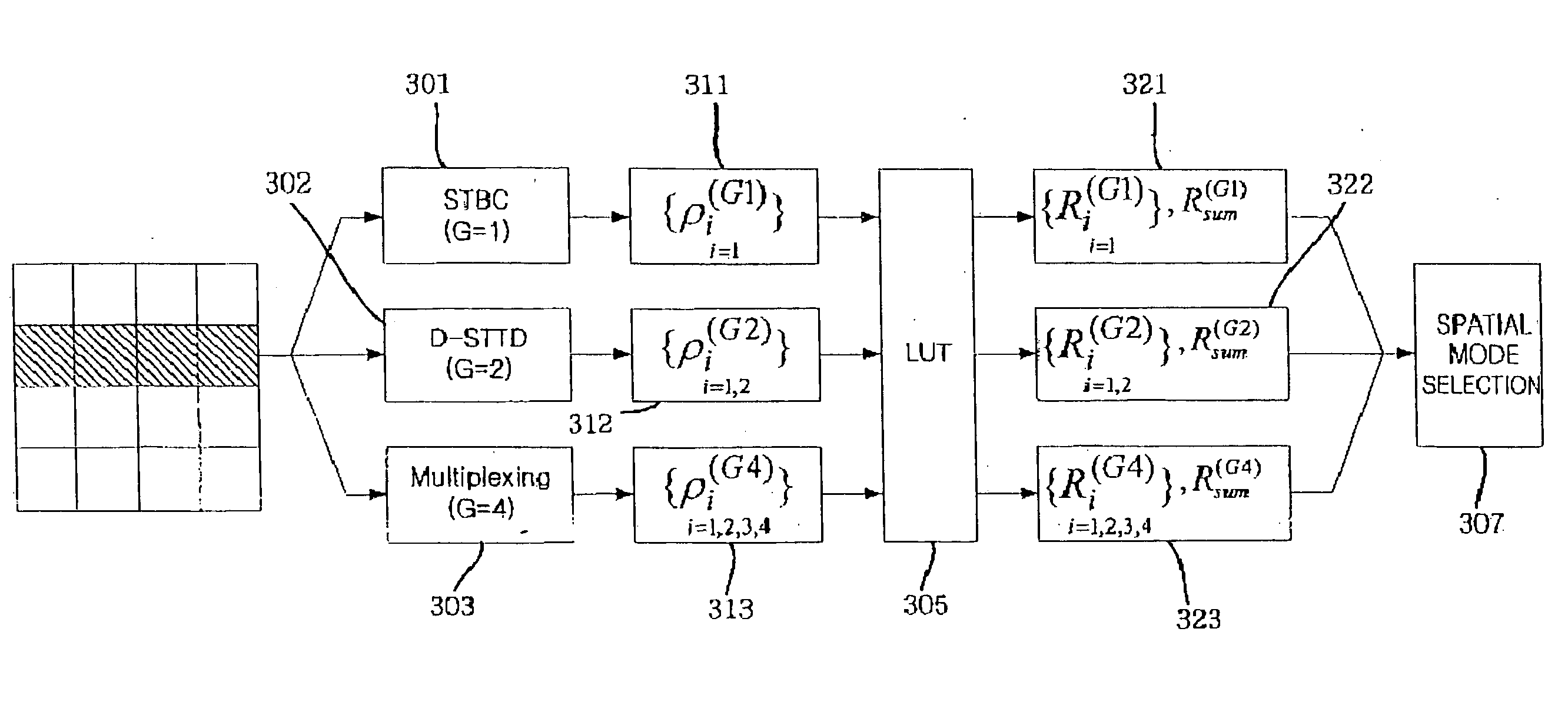
[0061]FIG. 6 is a conceptual diagram for a description of a process of selecting one of the spatial modes with G=1 and G=2 in the frequency domain according to the third embodiment of the present invention.

[0062] The third embodiment of the present invention selects spatial subchannels for the spatial modes 601 and 602 with G=1 and G=2 for each of a predetermined number of subcarriers, selects modulation schemes for the spatial modes referring to the look-up table 605 shown in Table 1, sums up data rates, as i...


PUM


Abstract

A data transmission method in a MIMO-OFDM communication system including at least one receiver for receiving a signal through a plurality of reception antennas and a transmitter for selecting a transmission channel using channel information being fed back from the receiver and transmitting a signal through a plurality of transmission antennas. The method includes selecting a spatial subchannel in which when bits are added by applying at least two spatial modes having different multiplexing gains for an individual subcarrier in a frequency domain, the minimum power increment is required during application of each spatial mode; allocating a spatial mode that requires the minimum total accumulated power, for each subcarrier; and selecting all subcarriers in the order of a subcarrier that requires the minimum power increment.

Description

PRIORITY [0001] This application claims priority under 35 U.S.C. § 119 to an application entitled “Transmission Method for OFDM-MIMO Communication System” filed in the United States Patent and Trademark Office on Sep. 24, 2004 and assigned Ser. No. 60 / 612,807, and an application entitled “Transmission Method for OFDM-MIMO Communication System” filed in the Korean Intellectual Property Office on Sep. 22, 2005 and assigned Serial No. 2005-88173, the contents of both of which are incorporated herein by reference.BACKGROUND OF THE INVENTION [0002] 1. Field of the Invention [0003] The present invention relates generally to an Orthogonal Frequency Division Multiplexing (OFDM)-based Multiple-Input Multiple-Output (MIMO) wireless communication system, and in particular, to a data transmission control method for an OFDM-MIMO wireless communication system. [0004] 2. Description of the Related Art [0005] A MIMO technique, which is technology for transmitting / receiving data using a plurality of...

Claims


Application Information

Patent Timeline
IPC IPC(8): H04K1/10
CPCH04B7/0626H04B7/066H04B7/0669H04L27/2608H04L1/0618H04L1/0675H04L25/0204H04L1/0003Y02D30/70H04L5/0044H04B7/0417H04B7/0426H04L27/2646
Inventor PARK, CHANG-SOONLEENAM, SEUNG-HOONJUNG, KOO-CHUL
Owner SAMSUNG ELECTRONICS CO LTD
Why Eureka
Try Eureka